How Does a Carburettor for a Tractor Engine Work?
This is a very basic general description, but we have to start somewhere!
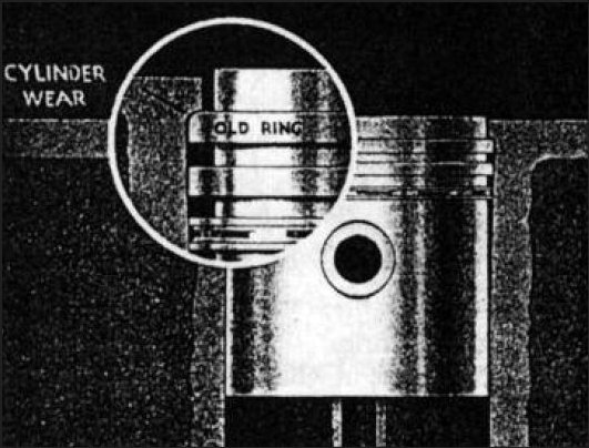
You know that the idea behind an engine is to burn fuel to create pressure, and then to turn the pressure into motion. A remarkably tiny amount of fuel is needed during each combustion cycle. Something on the order of 10 milligrams of fuel per combustion stroke is all it takes!Carburettorsngine runs properly. If there is not enough fuel mixed with the air, the engine “runs lean” and either will not run or potentially damages the engine. If there is too much fuel mixed with the air, the engine “runs rich” and either will not run (it floods), runs very smoky, runs poorly (bogs down, stalls easily), or at the very least wastes fuel. The carb is in charge of getting the mixture just right.
Nearly all older vehicles, and all small equipment like lawn mowers and chain saws, use carbs because they are simple and inexpensive.
The carburettor on a tractor is a good example because it is so straightforward. The carb on a tractor is simpler than most carbs because it really has only three situations that it has to cover:
- It has to work when you are trying to start the engine cold.
- It has to work when the engine is idling.
- It has to work when the engine is wide open.
No one operating a tractor is really interested in any gradations between idle and full throttle, so incremental performance between these two extremes is not very important. In a car the many gradations are important, and this is why a car’s carb is a lot more complex.
You can see the carb for various tractors in the diagrams following.
Here are the parts of a carb:
- A carburettor is essentially a tube.
- There is an adjustable plate across the tube called the throttle plate that controls how much air can flow through the tube.
- At some point in the tube there is a narrowing, called the venturi, and in this narrowing a vacuum is created.
In this narrowing there is a hole, called a jet, that lets the vacuum draw in fuel.
The carb is operating “normally” at full throttle. In this case the throttle plate is parallel to the length of the tube, allowing maximum air to flow through the carbo The air flow creates a nice vacuum in the venturi and this vacuum draws in a metered amount of fuel through the jet.
When the engine is idling, the throttle plate is nearly closed. There is not really enough air flowing through the venturi to create a vacuum. However, on the back side of the throttle plate there is a lot of vacuum (because the throttle plate is restricting the airflow). If a tiny hole is drilled into the side of the carb’s tube just behind the throttle plate, fuel can be drawn into the tube by the throttle vacuum. This tiny hole is called the idle jet.
Both the jets have screws restricting the fuel flow, these are simply needle valves. By turning them you allow more or less fuel to flow past the needle. When you adjust them you are directly controlling how much fuel flows through the idle iet and the main jet.
When the engine is cold and you try to start it, the engine is running at an extremely low RPM. It is also cold, so it needs a very rich mixture to start. This is where the choke plate comes in. When activated, the choke plate completely covers the venturi . If the throttle is wide open and the venturi is covered, the engine’s vacuum draws a lot of fuel through the main jet anon is a vertical instrument in general use on light
Commercial Vehicles, Marine Engines, Stationary Industrial Plant and various types of Mobile Agricultural equipment. The float the idle jet (since the end of the carb’s tube is completely covered, all of the engine’s vacuum goes into pulling fuel through the iets). Usually this very rich mixture will allow the engine to fire once or twice, or to run very slowly. U you then open the choke plate the engine will start running normally.
 Published in Journal No.41, Summer 2002, Alan Dunderdale
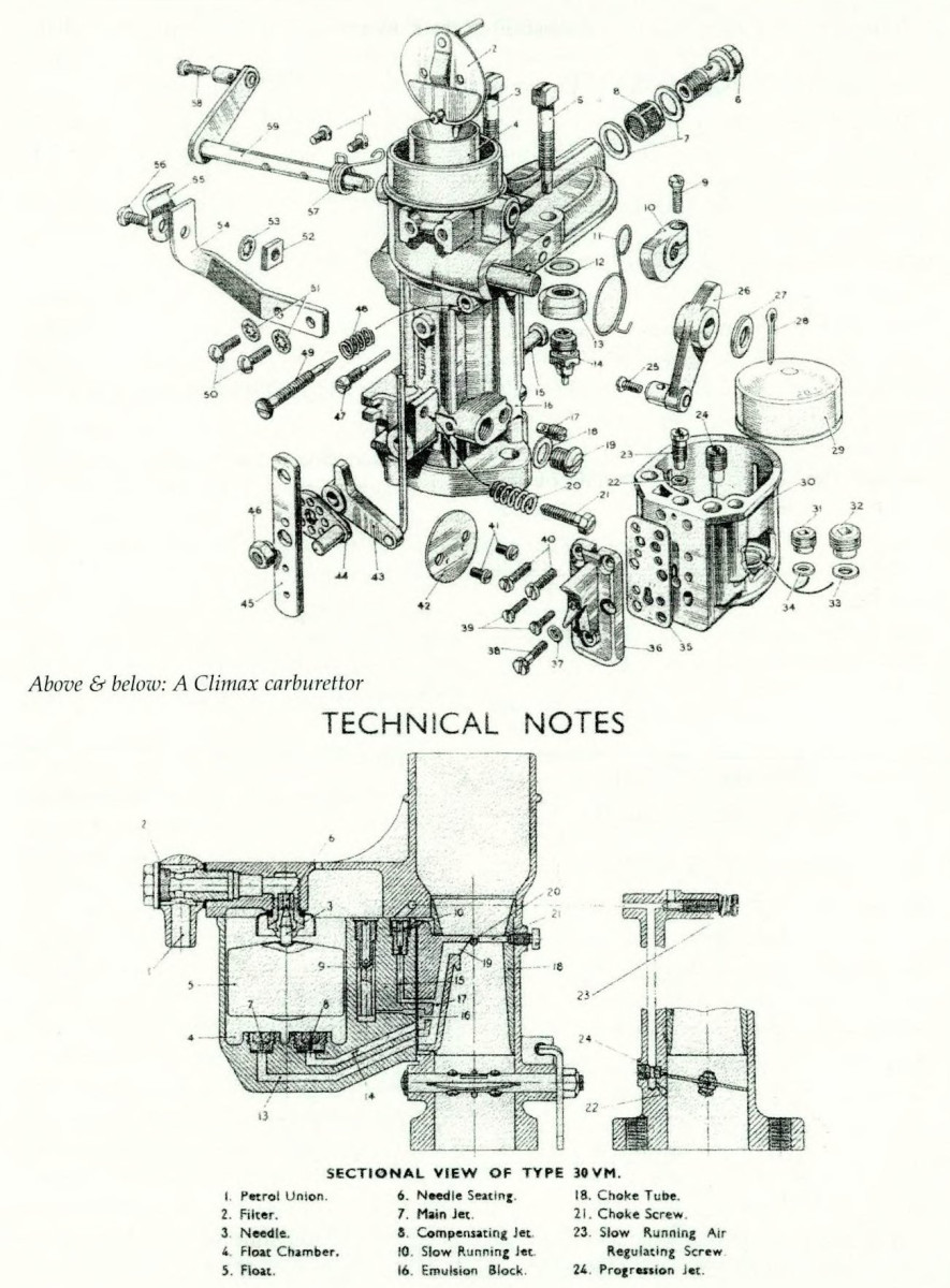
FERGUSON TRACTOR CARBURETTORS
In this article I have tried to cover most of the carbs as fitted to Ferguson tractors. This is NOT a technical article, but it is intended only as an informative general guide to carburettors.
I have included the combine harvester carb, 30VEA as some of these engines have been used as replacements for the Ferguson engines.
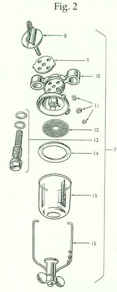
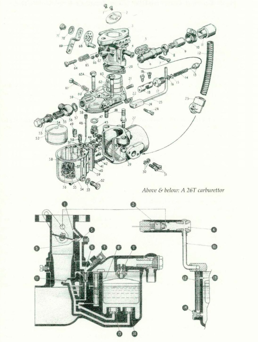
The Zenith 24T Carburettor as fitted to the Ferguson Range of Tractors (1947 • 1949)
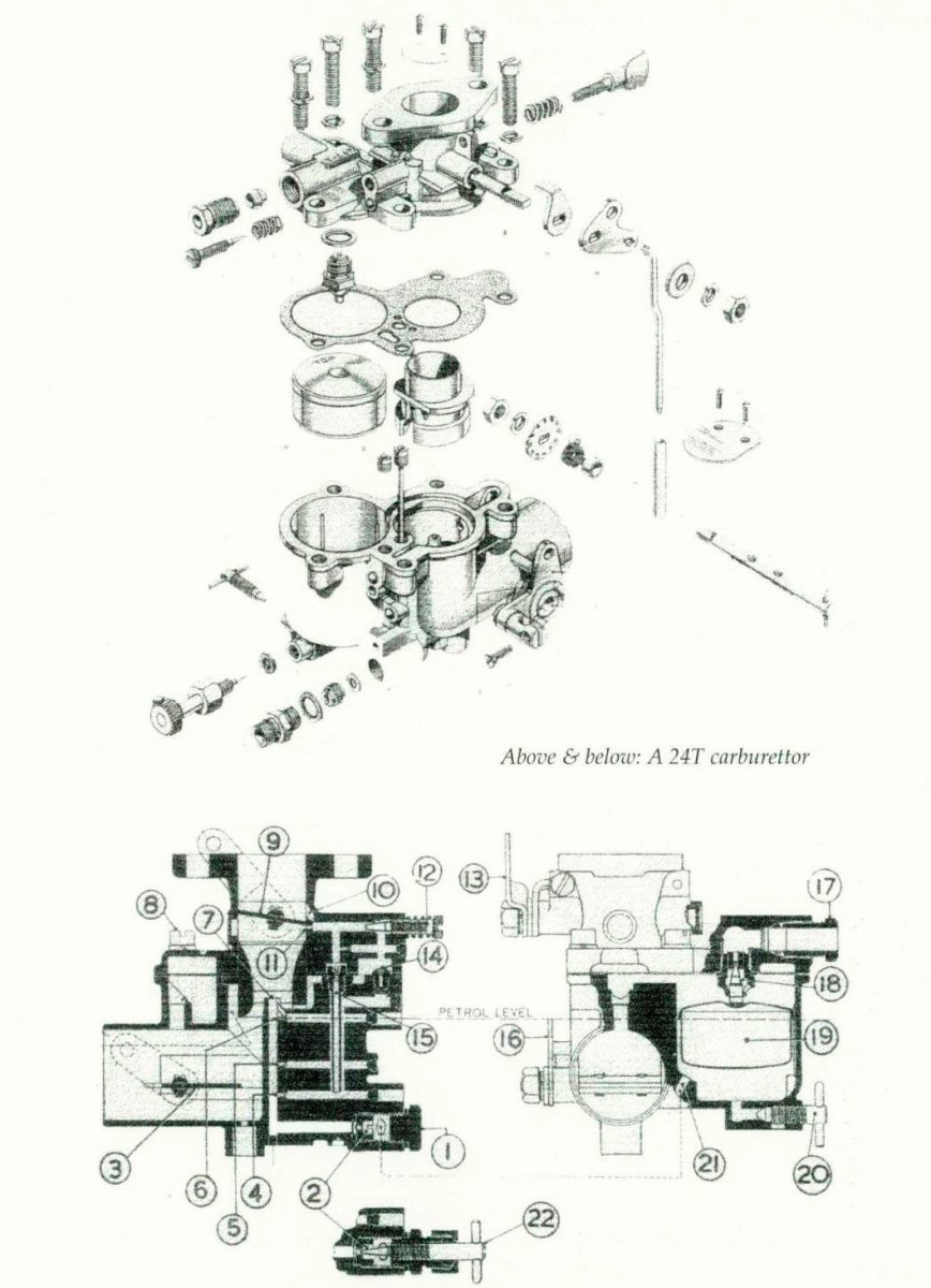
The 24T-2 Carburettor shown in cross section is a vertical instrument in general use on light Commercial Vehicles, Marine Engines, Stationary Industrial Plant and various types of Mobile Agricultural equipment. The float chamber is offset in order to keep it as close as possible to the main discharge tube, thus ensuring high angle operation in any direction without flooding, or stalling. The instrument can be arranged to take all air through the main intake, which is invariably protected, by an air cleaner. This feature is called for when working under dusty conditions close to the ground, if long life and reliable service are to be obtained.
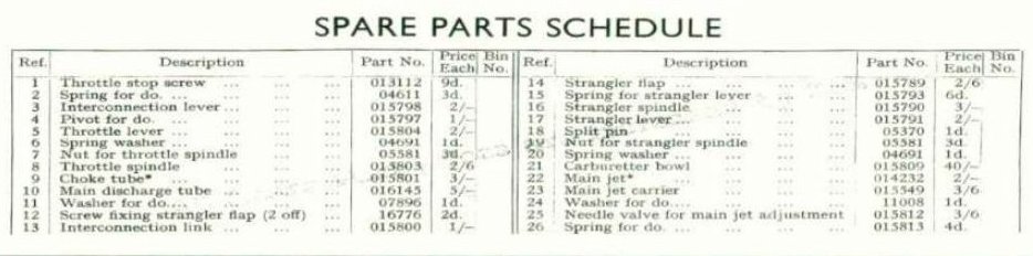
The carburettor consists of two main castings, the upper or barrel portion being secured to the lower bowl portion by five screws, one of which is shown (8).
In order to keep this carburettor as simple as possible we have used One principal jet and a slow running jet.
Suitable air bleeding is arranged to atomise the fuel and to maintain correct mixture strength under all conditions of engine operation. The above drawing shows the principal, or main jet (2) covered by the large hexagon plug (1). The slow running jet is also shown (15). The air bleeding to the main iet system is controlled by the air jet (14), and this air supply is taken from the main air intake. It will be noticed that this air issues from the holes (4), (5) and (6), at high engine speeds when the fuel In the main discharge tube (7) falls to its lowest level. Fuel metered by the slow running jet (15) is atomised by an air supply taken through the main air intake and controlled by the screw (12). This mixture issues through the idle discharge channel (10) and the progression orifice (11). The float chamber contains a normal type float (19) and the usual combined needle seating valve (18). The latter part is usually fitted with one washer, but two washers can be used if it is desired for any reason to lower the fuel level in the float chamber.
MAIN ADJUSTMENT
The combination of choke tube, main jet and air jet will be found correct for the engine to which the instrument is fitted and it should not be necessary to alter these parts. When dealing with ordinary running trouble. Cleanliness is the keynote for good results, Take special care to use a suitable screwdriver when removing the main jet in order to prevent damage to the thread in the carburettor casting. A gasket must always be used between the two halves of the carburettor.
SLOW RUNNING ADJUSTMENT
This should be carried out when the engine is hot; the minimum running speed is usually set around 550/600 rpm. A spring loaded adjusting screw is provided close to the throttle lever by means of which the exact throttle opening can be adjusted for idling. The head of this Screw should be turned clockwise to increase the idle speed and vice versa. The slow running mixture screw (12) will provide a richer idle mixture if turned in a clockwise direction by reducing the supply of slow running air. On the other hand if there is evidence of rich running, Le., black smoke from the exhaust when idling, this screw should be given a quarter, or one half turn in an anti-clockwise direction. The usual setting is about one complete turn open from channel (10) the full home position, but of course this varies slightly from one engine to another.
COLD STARTING
The rich mixture necessary to meet this condition is provided by closing the choke, or air strangler (3), and at the same time the throttle lever should be set about one-third of its full movement open. A few sharp pulls over compression with the starting handle will give an immediate start even in the coldest condition, provided all engine details are in order. Never leave the throttle in the slow-running position when starting a cold motor.
HOT STARTING
When the engine is hot or warm, the choke is not required and the throttle position is not important. If the engine does not immediately respond set the throttle open, as continued rotation might bring about an over-rich condition in the cylinder. When dealing with such a condition, it is advisable to remove the sparking plug and also the air cleaner. A few rotations of the crank-shaft will restore normal conditions in the cylinder, and upon replacing the sparking plug, the engine will fire and run in response to further rotation, provided the plug is clean and dry.
GENERAL
In most cases filter gauze is provided and this should be cleaned periodically by first of all removing the brass plug fixing the petrol pipe to the carburettor. Take care to replace the fibre washers when reassembling, placing one washer on each side of the petrol pipe banjo. If the complete carburettor is removed and dismantled for cleaning purposes, it is a good plan to blow it out on a compressed air line. When replacing the
instrument take care to use a thin flange gasket, as if a thick gasket is used it wilt tend to squeeze out, causing the flange on the carburettor to bend, and this may allow an air leak. Check the flange for damage of this nature, which can be trued up in the usual manner with a file. After replacing a carburettor, always cheek the air strangler, or choke, to make quite certain it closes completely when the control is operated and also that it opens fully, these points being most important. The throttle lever, if controlled by a speed governor, should work quite freely. Paraffin engines must be turned over to petrol for a few minutes before stopping in order that petrol will be available in the float chamber for re-starting. A drain tap (20) is provided on these models to drain off paraffin from the float chamber, if necessary. The air strangler plate (3) may be of the fixed type as shown, which usually has a small air hole, this being provided to ensure continuity of running after the first fire when starting under cold conditions. In certain of these carburettors, a fully automatic spring loaded strangler flap is used. The method of operation is the same in all cases. It is possible to use a variable main jet on certain engines this part is shown (22), and can be supplied upon request.
The makers’ adjustment of the carburettor gives correct mixture strength for all conditions, up to about 3,000 feet above sea level. When operating at high altitudes, it may sometimes be necessary to deal with rich running and loss of power. In such cases, one size smaller main jet will usually be found beneficial, however, if the power loss is still appreciable, it may be an advantage to fit a larger choke tube in conjunction with a suitable main jet.
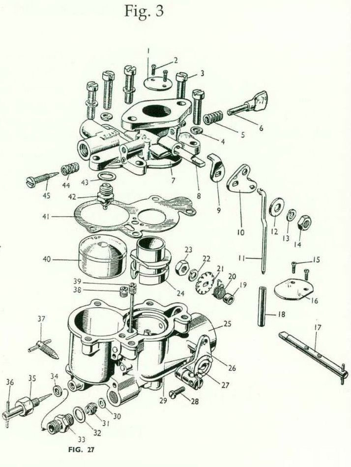
Diagrammatic Section of Carburettor, Type 28G (with adjustable jet)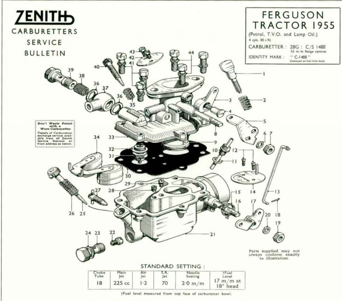
GENERAL DESCRIPTION
The 28G carburettor, shown in the sectional view, is a vertical unit of robust design and construction, capable of high-angle operation.
OPERATION
Petrol enters the carburettor at the banjo union (7) and passes into the float chamber through the needle and seating assembly (14). It will be observed that the float chamber Of bowl is of special construction, embodying a dual float (12) system; as fuel rises in the chamber the floats will be lifted unti!, at the predetermined level, they will press the needle on to its seating and thus prevent the entry of more fuel.
The channel (2) in the illustration is plugged as shown. On this model the air vent to the float chamber is taken from the inside of the air intake, via the annular space round the choke tube, to the carburettor bowl.
From the float chamber the petrol will pass the tip of the adjusting needle (13), through the main jet (19), and then rise in the main discharge tube (9), slow-running jet (10) passage and main air bleed (6) channel to the correct level.
STARTING FROM COLD
By extending the appropriate control. the strangler (18) turns and closes the air intake of the carburettor. In so doing the interconnection rod (8) will automatically open the throttle (5) to a degree found most suitable for starting purposes. The engine is
then turned over and a very rich mixture will pass to the engine to provide the necessary fuel for starting purposes. Once the initial fire has been obtained, the extra depression on the engine side of the strangler will cause the spring blade in the strangler to open and close rapidly with the engine pulsations. This is to ensure that the engine continues to run at a good speed once the initial fire has been obtained. As soon as normal working temperature has been attained the strangler is released and, with the throttle in the normal idling position, fuel is delivered by the slow-running system.
IDLING
Petrol is drawn from the well beneath the idling jet 10), is measured on passing through the jet and then enters the bore of the carburettor through the idle drilling (3) on the engine side of the throttle. Progressive opening up from idling is ensured by the provision of a second feed hole, slightly below the idle outlet (3).
MAIN CARBURETTOR
When the throttle is opened, petrol in the channel beneath the air bleed (6) will be drawn into the engine, and the main air bleed will now be effective over the whole speed range. Petrol from the float chamber is metered by passing through the main jet (19), after which it enters the bore of the carburettor from the tip of the main discharge tube (9). At this point the fuel is taken up by the air from the intake of the carburettor, and the mixture then proceeds to the engine via the choke tube (11).
As with all carburettors, the keynote of reliable and efficient service is absolute internal cleanliness. If the float chamber drain tap (15) is not utilised when starting from cold, it is recommended that it should be opened occasionally when the tractor is in use, in order to clear away any foreign matter or water which may have collected at the bottom of the float chamber.
The combination of choke tube, main jet and air jet as specified overleaf will be found correct, and it should not be necessary to alter these parts when dealing with ordinary maintenance. It will be observed, however,
that the main jet is adjustable by means of the needle (13) and very careful setting of this is necessary for local conditions.
The idling adjustment is a matter of setting the throttle stop screw (4) and the air regulating screw (1) to ensure that the engine speed and fuel mixture are correct to obtain steadiness when idling. Turning the regulating screw (1) clockwise provides a richer mixture for idling, and vice versa.
In any case of difficulty, the Zenith Technical Information Centre is at your disposal, or the nearest official Zenith service station should be consulted.
Diagrammatic Section of Carburettor, Type Climax
The 30VEA carburettor is an updraught model of the V type Zenith carburettor incorporating an easy starting device, and has been specially modified to make it completely dustproof. All the air used by the instrument is taken from inside the air intake, and there are no exterior holes open to the atmosphere. (The diagrammatic drawing right does not illustrate this feature but shows a normal Zenith model, although it is correct in all other respects).
THE STARTING DEVICE
When starting from cold the control knob on the dashboard is pulled out so that the valve 2 opens (as shown in the diagram.)
When the crankshaft turns over the accelerator pedal must not be depressed, as it is essential that the throttle should not be opened beyond the normal idling position for starting purposes. When the engine rotates with the throttle in this position the depression created will be concentrated upon the outlet 1 on the engine side of the throttle. It will also be apparent at the venturi 4 and in the communication tube 10, with the result that air is drawn through the venturi and petrol from the control jet 12 and starting jet 14.
The petrol will meet the air at the venturi and be broken up to form a rich starting mixture, which then passes into the induction pipe through a channel above the throttle.
A weaker mixture may now be used, but even so it must still be richer than that provided by the main carburettor. Once the petrol in the starting well has been consumed it will be replenished with a measured quantity of fuel from the float chamber through the starting jet 14. With the bottom of the control jet tube 12 uncovered, however, the depression on this tube will be partly broken by the air leak at 13. This gives the desired weakening off once the cold engine fires and continues to run.
When the engine reaches a normal working temperature, the extra fuel supplied by the starting device can be dispensed with. The starting control knob is released and the valve 2 doses, thus cutting off the depression that previously caused the starting device to operate.
SLOW-RUNNING
With the engine running and the throttle in the idling position a depression will be concentrated upon the outlet 1, and consequently also on the slow-running jet 6. As a result petrol will be drawn from the well beneath the jet, measured on passing through, and proceed to outlet 1; here it will meet the air passing the edge of the throttle and be carried into the engine as a suitable mixture for idling purposes.
At the throttle edge there is a further outlet 5, which breaks into the slow-running passage. Upon the throttle being opened from the idling position this drilling will enable an additional mixture to be provided to ensure a progressive get-away from slow running. (This explains the name of the progression jet 3.)
Upon the throttle being opened still further the depression will be concentrated upon the nozzle of the emulsion block 11, which projects into the smallest part of the choke tube. This will result in petrol being drawn from the main channel in the emulsion block, which is supplied by the
passage beneath the slow-running jet 6 and the well of the capacity tube 8. This reserve is provided to ensure immediate get-away when the throttle is opened. Once this reserve of petrol is used the supply will be direct from the float chamber, being metered through the main jet 16 and compensating jet 15 before leaving the nozzle of the emulsion block.
lt will be realised that as soon as the petrol in the float chamber falls below the predetermined level the floa t will fall with it, thus permitting the needle 9 to drop away from its seating, and petrol will pass into the chamber from the fuel line.
The petrol feeds the carburettor through the banjo, filter and filter piug as shown in the diagram. As it enters the float chamber it win raise the float and push the needle on to its seating, thus cutting off further supplies when the correct level is reached.
SLOW-RUNNING ADJUSTMENT
There is an adjustable air release to the slow-running jet which is controlled by the screw 7; this varies the quality of the idling mixture. When the screw is turned clockwise there is a greater depression upon the slow running jet, and as a result a richer mixture is obtained for slow-running.
Alternatively, if the screw is turned in an anticlockwise direction there is a reduced depression upon the jet, and consequently less petrol is drawn through it.
To adjust the slow-running speed (I.e., the volume of the mixture) the throttle stop screw at the throttle lever may be turned clockwise, causing the throttle to open wider and give a faster idling speed. On the other hand, if the screw is turned anticlockwise the throttle will close to a greater degree and reduce the idling speed. It will therefore be seen that to obtain good slow-nmning it is necessary to adjust both the air regulating screw 7 and throttle stop screw.
DIFFICULT STARTING
Many factors have to be considered when there is difficulty in starting an engine from cold. After all other possibilities have been eliminated the following points should be checked in the carburettor
ENGINE FAILS TO FIRE
A too-weak mixture is the most probable cause, and adjustments to the control jet and starting jet are indicated. The control jet measures the petrol flow until the fuel in the well is consumed, and thereafter affects the depression on the starting jet. First, try larger starting jets, but failing improvement resort to increased sizes of control jet. Engine fires but then stops.
Over-rapid weakening-off is the fault here, and correction is to be found by increasing the size of the starting jet. (N.B.The concentration of the depression upon the starting device is most essential. Make sure, therefore, that the throttle is closed to the idling position when the engine is being started).
When the carburettor is worn it will be impossible to obtain good slow-running, but it must also be remembered that there are other factors which, quite apart from the carburettor, have an influence upon slow running. These include joints that are not airtight, worn valve guides, valves not seating, over-advanced ignition, incorrect setting of sparking plug points, etc.
GENERAL
To remove the float-chamber unscrew the two bolts, when it will be found that the main and compensating jets inside the bowl have square recesses into which the squared end of one of these bolts can be inserted in order to take out the jets.
Do not pass anything through the drillings of the carburettor or the jets that is at all likely to damage them. The safest way of clearing an obstruction is to swill the part in petrol and clear with air pressure.
Periodically inspect the emulsion block screws, needle seating, jets etc., and see they are all tight and secure.
It has now been observed how the petrol reaches the jets and channels. The fuel will occupy the position described all the time the engine is not running.
STARTING
Let it now be supposed that the engine is to be started from” cold.” The strangler control on the dashboard is extended, which causes the strangler flap to close off the air intake of the carburettor.
With the ignition switched on, the engine should now be turned over by means of the starter, ensuring at the same time that the throttle control is not opened from the closed position. The necessary part opening of the throttle for starting having been provided automatically by the interconnection mechanism between the strangler and the throttle. Practically all of the depression caused by the rotation of the engine is now concentrated upon the progression and the slow running outlets (22 and 24), and because of the partly opened throttle plate, upon the outlet (19) of the emulsion block. Very little air enters and consequently a very rich mixture as required for — cold ” starting purposes is made available to the engme.
The engine will now fire, and as soon as it does so, the engine speed will increase and heavier depression will cause the valve in the strangler flap to open. The result will be to weaken the mixture and ensure that the engine continues to run once it has fired,
As the engine warms to its work the strangler must be released and the engine will be operating on the normal mixture.
NORMAL OPERATION
With the throttle closed down to the idling position the mixture will be supplied from
the slow running jet (10). Depression will be concentrated upon the outlet (22) and upon the slow running jet (10). Here there is a controlled depression fall because of the leak at the slow running air regulating screw (23).
Petrol will be drawn from the well beneath the jet, measured on passing through, before continuing to the throttle edge.
At the throttle edge there is a further outlet (24) which breaks into the slow running passage. Upon the throttle being opened from the idling position, depression will be concentrated here and a progressive get-away from slow runnmg is assured.
Upon the throttle being opened still further, the depression will be concentrated upon the nozzle (19) of the emulsion block which projects into the narrowest part of the choke tube. This will first result in petrol being drawn from the passages (17, 16, 14, 13 and 9), as there must be a ready reserve of petrol available for instant acceleration.
The source of petrol supply is eventually through the main and compensating jets (7 and 8). It will be observed that the petrol in the well of the capacity tube (9) has been consumed, and as the top of the well is open to atmosphere, petrol issuing from the compensating jet along the passage (14) will now be broken up at (16) by air from the capacity tube. Petrol issuing through the main jet (7), along the passage (13) will meet the emulsified petrol from the compensating jet in the common channel (17). This will tend to break up the petrol from the main jet also. The supply from both sources will then be drawn from the emulsion block nozzle into the choke tube.
Published in Journal No.41, Summer 2002, Alan Dunderdale

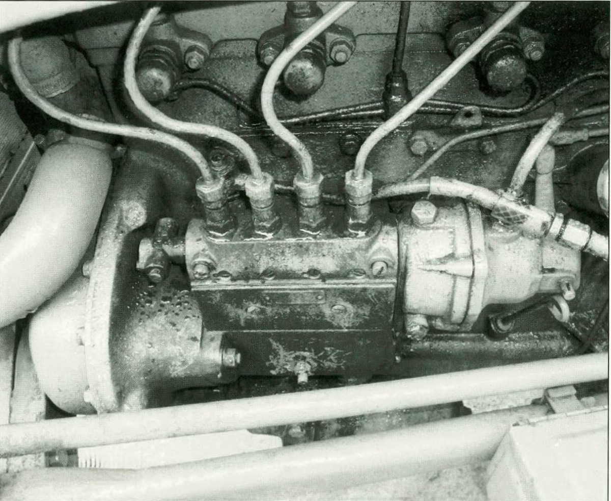 The TEF20 injection pump.
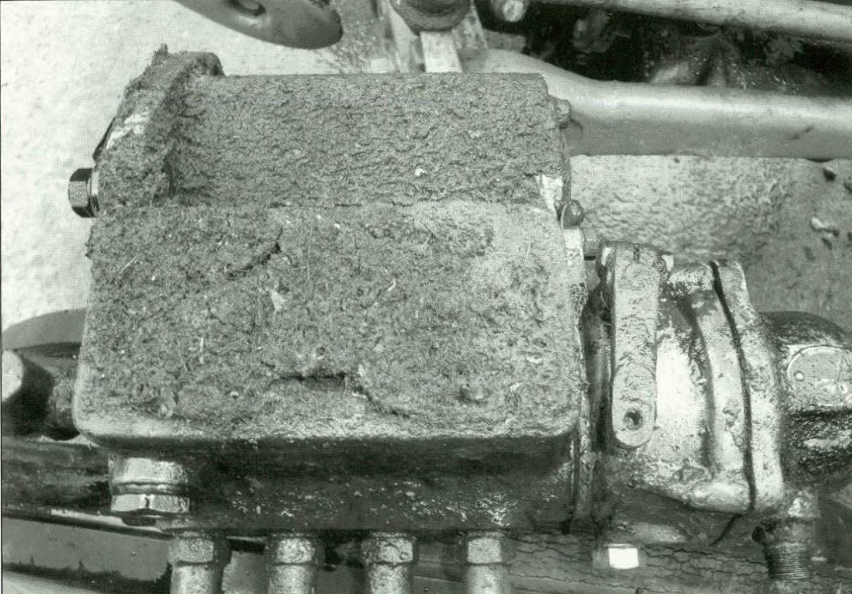 Looking at the rear of the injector pump after removal.
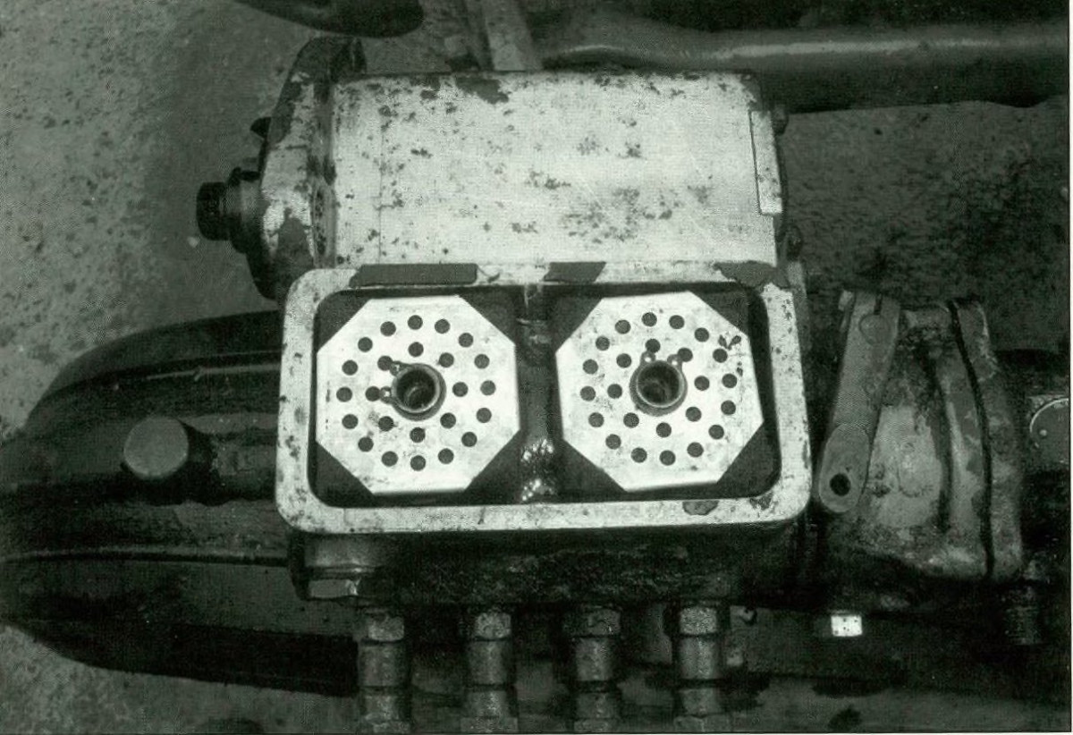 With the rear plate removed the two felt filters are visible.
 The early pump drive
 The later uni-direction drive