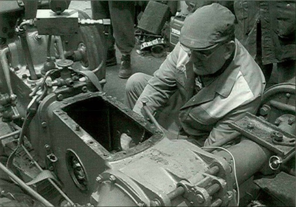
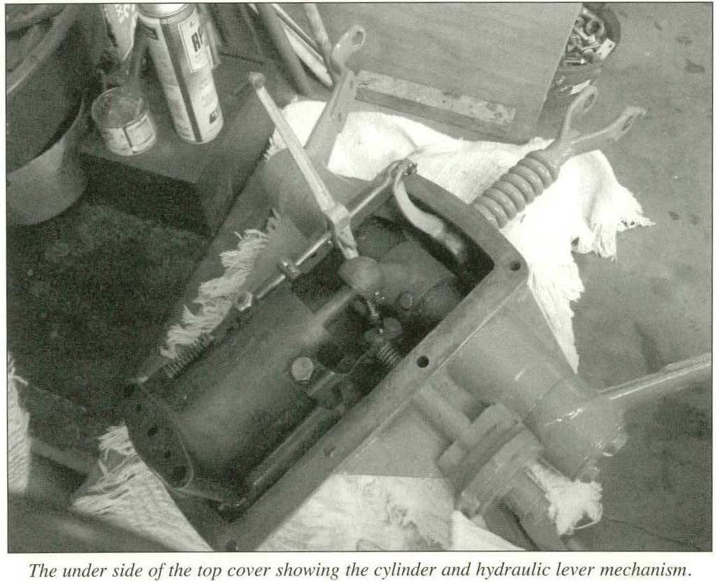
These notes, by Harry Jeffery, may be useful to those of us who still use our TE-Ds (which run on Tractor Vapourising Oil or TVO), TEHs (Lamp Oil or LO) or those engines converted from petrol to TVO, and wish to get the best out of these fuels whilst minimising sump oil dilution.
In the mid fifties a Service Bulletin was issued detailing modifications which would improve the perfomance of VO engines and its ability to vapourise fuel efficiently. The main items to note were:-
- Use the correct spark plug with correct gap. Set wider rather than closer, say .030″.035″ for Va/La (.032″ for va conversion)
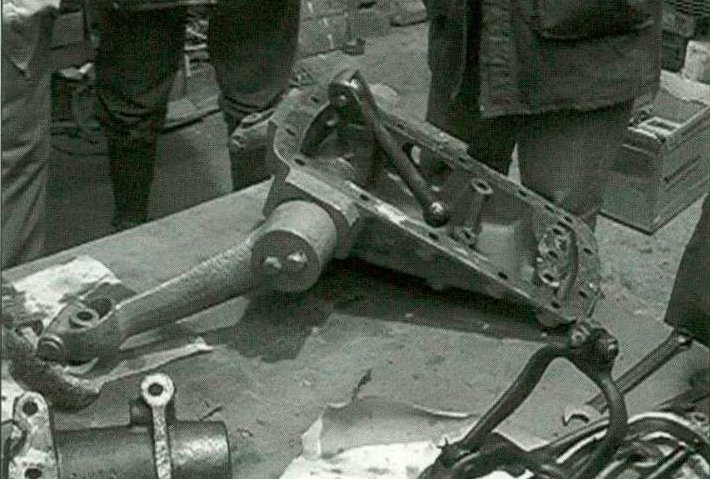
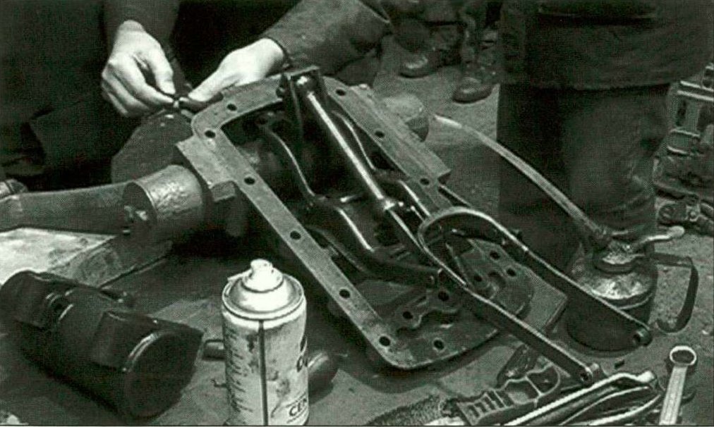
- Make sure that the exhaust manifold is completely free of all carbon deposits, especially those moist oily ones. This may be done by burning out with an oxy/act. torch or by shot blasting. A combination of the two proved to be the most effective. Always use a non abrasive grit.
- Make (from aluminium sheet) a supplementary shield to fit under the existing standard manifold shield, thereby deflecting
the fan draft away from the manifold. For the same reason, fit another shield in front of the carburetter throat.
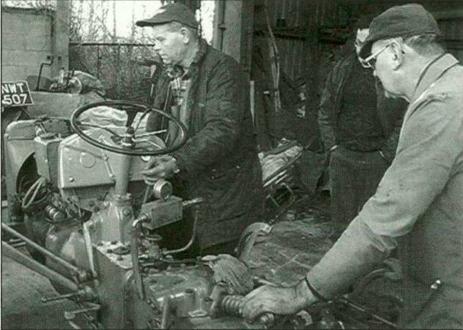
In addition, see that the ignition is in good order with correct timing and the carburetter correctly adjusted according to type. The Zenith 24T-2 always gave best results. The Zenith 28G was a menace unless modified. The Holley 859A carburetter, mainly fitted to the 80mm engines, was not so reliable as the Zeniths.
For normal work the Zenith 28G requires 1 turns for the main jet on petrol, another turn on TVO and yet another turn for lamp oil, whereas the 24T-2 main jet setting remains the same for all three fuels. However, the main jet size on the ‘Fully Variable Type’ 24T-2 is 1 mm for petrol and 1.05mm for Va/La fuels.
The petrollTVO conversions should be fitted with a different sparking plug [Champion L.8] to the production TVO/LO engines. Full details can be found in the workshop service manuals available from Landsman’s Postal Bookshop or Massey-Ferguson. Editor)
Published in Journal 15, Vol.4 No.3 Winter 1991, Harry Jeffery.
Formula for T. V.O. Substitute
5 gallons 28 second Central Heating fuel
1 gallon Petrol
1/2 pint Universal Engine oil.
(Journal 2, Winter 1986/87)
FE35 with TVO Engine
Dear Sir,
I recently acquired a Massey-Ferguson FE 35 tractor with a TVO engine. The previous owner used to run it on 6 parts of paraffin to 1 part of petrol. The tractor is used for light duties, such as hauling logs and a trailer. I have only run it on petrol, but have found the fuel consumption to be high. I should be grateful if you would advise me if the paraffin mix is acceptable. If not, what should I use to improve the fuel consumption?
Thanking you in advance of an early response. R P Thatcher
Engines designed to run on Tractor Vaporising Oil (TVO) or paraffin (lamp oil or LO) have a much lower compression ratio than those designed to run on petrol. It is thus quite usual for such engines not to be fuel efficient when running on petrol alone.
Before TVO became available, on this farm from 1928 we always added petrol at the rate of 1 gallon to 4 of paraffin. TVO was a great improvement but sadly we have had, in recent years, to revert to our pre-war practice. We usually add a pint or two of diesel or a very light oil such as Castro I GTX to aid upper cylinder lubrication.
It is always important to ensure your engine is at proper operating temperature before turning over to paraffin. Lamp oil engines, not usual in UK, are designed to run on straight paraffin. Avoid prolonged idling or very light loadings at all times when on paraffin. Such engines are best at normal operating loads. Hard work but not overloading is ideal.
It is also worth checking that your carb, aircleaner and related pipework are in good order, clean and properly serviced.
Service Department
Letter and Reply published in Journal 21, Vol 7 No.1 Spring 1994