Author Archives: Peter

Starter Motor Switch 🔑

Service Article for TE20 Spark Ingnition and TEF 20 Diesel Engines

Starter Motor Switch

12 Volt
Petrol. V.O. and L.O. Tractors lucas Model ST.18.
Service No. 76418A
Mechanical type operated by gear lever.

6 Volt
Service No. 76407

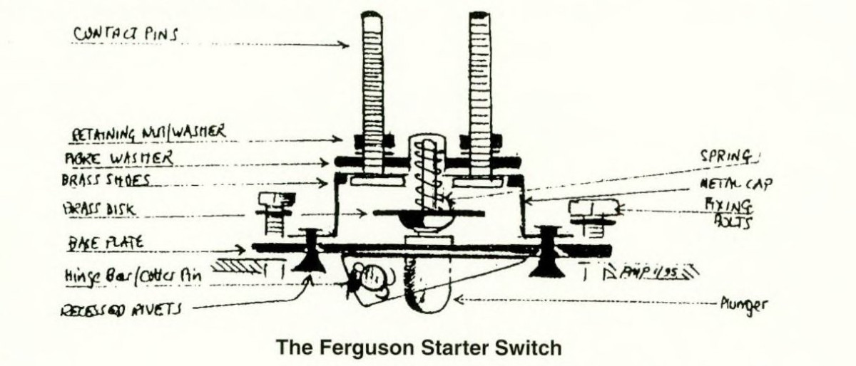
The starter switch is mounted on the clutch portion of the transmission housing, just forward of the steering column, in a casing of its own that is held by four bolts. The contact points are sealed against dirt and moisture, and are actuated by a plunger that projects to the inside of the clutch housing. The plunger in turn is actuated by a rocker which is connected to the transmission reverse gear shifter rail by means of a strap (see Fig. 1).

Reverse movement of the transmission shift rail causes the rocker to force the plunger upward against the switch and makes contact between the two points.

The above movement is brought about by raising shift lever and moving it forward to the right, thus preventing the operation of the starter motor when a gear is engaged.

Service

1 Remove the three wires connected to switch (battery, key and starter), and the four bolts holding switch.
2 Raise and tilt the switch forward to remove pin. To prevent the connecting link from switch to rail from dropping down, secure same with a piece of wire or string. The pin can now be pulled and the switch replaced.
3 The switch case is riveted and should inspection be desired, rivets can be cut and replaced without difficulty. The switch must be sealed against the entrance of dust, which prevents a good electrical contact.

NOTE: A switch of improved design, facilitating inspection of contacts by the removal of 3 set screws was incorporated on later production tractors.

4 To adjust the starter switch move backward or forward the slotted mounting bolts until· correct engagement or disengagement is obtained.

The wiring on the tractor is comparatively simple, but must be maintained in good condition to prevent hard starting and electrical difficulties. The battery cables are designed to carry between 200 and 400 amps. However, if the terminal contacts are not kept clean and tight, the current carrying capacity is greatly reduced and starting trouble results. It is essential to maintain good earth connections for battery, starter and dynamo.

DIESEL TRACTOR

Lucas Model ST.950

Service No. 76411 B
Solenoid type, energised by electrical contact switch on Starter Motor operated by gear lever.

Tractor TE-F 20

The gear change lever operates the starter through the reverse shifter rail which is linked at the front to a cross shaft assembly mounted on the front portion of the clutch housing and connects to the pilot switch on the starter motor.

A spring loaded safety button on the right hand side of the transmission casing must be depressed before the gear lever can be moved into the starting position. This prevents inadvertent operation of the starter motor.

When the gear lever is moved to ‘start’ and the safety button has been depressed, the lower forked end of the operating lever at first slides the drive outwards along the armature shaft extension until the pinion is in mesh with the flywheel, the upper end of the lever contacts the pilot switch. This energises the solenoid of the main starting switch whose contacts close and connect the starter motor to the battery. Immediately, the armature rotates at a high speed and moving member (E) acting under the force of inertia, is screwed hard against the clutch assembly. A torque is then applied from the starting motor armature to the engine flywheel via the central core (A) moving member (E) the clutch assembly and barrel unit (G)

After the engine has fired and the gear lever has been returned to neutral, the rotating drive is brought rapidly to rest by the pressure of brake plate (D) against a Ferodo brake plate.

It will be seen that damage to the flywheel gear and pinion teeth is only likely to result from misuse or mal-adjustment.

In the event of unsatisfactory operation check the electrical circuit before any attempt is made to adjust the mechanical linkage.

If the pilot switch is in order, follow these instructions in order laid down, to ensure that the starter linkage and pilot switch brackets are correctly adjusted.

ADJUSTMENT OF ROD MECHANISM

Disconnect the operating rod by removing the clevis pin and adjust the rod in length until it just takes up all the free movement of the starter’s operating linkage.

N.B. In no circumstances should the operating rod be lengthened beyond the free movement of the starter operating linkage as this will move the pinion away from its rest position, which will prevent “the starter armature brake operating, and reduce the pinion “out of mesh” clearance, wh~ch may result in the pinion fouling the gear ring.

This adjustment may be all that is required to ascertain this reconnect the operating rod and re-engage the gear lever to check and the starter will operate. If there is no improvement and if all the free movement has already been taken up proceed to check the adjustment of the pilot switch as follows:

Adjustment of Pilot Switch Bracket with Relation to PinIon Travel

After assembly of the pre-engaged starting motor an important adjustment has to be made before the starter can be safely mted to an engine. The adjustment concerns the position of the pilot switch bracket with relation to pinion travel. That is, the pilot switch bracket is adjusted so that at the instant of closure of the pilot switch contacts, the fork operating lever must have moved the pinion 51;

(15.8 m/m) outwards along the armature shaft extension.

Initially the pilot switch bracket is accurately positioned during assembly of the starter at the factory. But, and this is very important, in all cases where a pilot switch is replaced or the switch bracket disturbed for any reason at all the bracket must be accurately repositioned.

The adjustment procedure is as follows :-

A test lamp and battery should be wired in series with the pilot switch terminals in order to determine the instant of contact closure.

To adjust, slacken the four pilot switch bracket securing screws, actuate the operating lever and position the bracket so that the pinion travel is 51; at the instant of closure of the pilot switch contact.

The main feature of the pre-engaged starter fitted to this type of tractor is that the pinion is in mesh with the flywheel ring gear prior to the tongue being applied.

The drive of the pre-engaged starter comprises four main assemblies.

1 A central core (A) keyed to and made to slide along a straight-splined portion of the armature shaft extension.
2 At the armature end of the central core, an operating bush (8) is spring loaded between the shoulder of helically splined portion (C) and brake plate (D).
3 At the pinion end of the central core, a clutch assembly is held between moving member (E) and ring nut (F).
4 Enclosing the clutch assembly, the pinion and barrel unit (G) with cushioning spring (H) and thrust washer (I); is secured by a circlip (J) located on the armature side of retaining washer (K). At the driving end, the pinion is supported by a steel backed bronze bush. The clutch is made up of inner plates and outer plates, arranged alternatively. The inner or driving plates are keyed to moving member (E) whilst the outer or driven plates are keyed to slots in the enclosing barrel unit.

The clutch protects the motor from overload in the case of a backfire. Also, it prevents the motor being driven by the flywheel if the pinion fails to disengage alter the engine has fired, as only the barrel unit and outer clutch plates will continue to rotate at speed. See Fig 2.

Adjustment of Pilot Switch Bracket with Relation to PinIon Travel

After assembly of the pre-engaged starting motor an important adjustment has to be made before the starter can be safely mted to an engine. The adjustment concerns the position of the pilot switch bracket with relation to pinion travel. That is, the pilot switch bracket is adjusted so that at the instant of closure of the pilot switch contacts, the fork operating lever must have moved the pinion 5/8″; (15.8 m/m) outwards along the armature shaft extension.

Initially the pilot switch bracket is accurately positioned during assembly of the starter at the factory. But, and this is very important, in all cases where a pilot switch is replaced or the switch bracket disturbed for any reason at all the bracket must be accurately repositioned.

The adjustment procedure is as follows :-

A test lamp and battery should be wired in series with the pilot switch terminals in order to determine the instant of contact closure.

To adjust, slacken the four pilot switch bracket securing screws, actuate the operating lever and position the bracket so that the pinion travel is 5/8″, at the instant of closure of the pilot switch contact.

The main feature of the pre-engaged starter fitted to this type of tractor is that the pinion is in mesh with the flywheel ring gear prior to the tongue being applied.

The drive of the pre-engaged starter comprises four main assemblies.

1 A central core (A) keyed to and made to slide along a straight-splined portion of the armature shaft extension.

2 At the armature end of the central core, an operating bush (8) is spring loaded between the shoulder of helically splined portion (C) and brake plate (D).

3 At the pinion end of the central core, a clutch assembly is held between moving member (E) and ring nut (F).

4 Enclosing the clutch assembly, the pinion and barrel unit (G) with cushioning spring (H) and thrust washer (I); is secured by a circlip (J) located on the armature side of retaining washer (K). At the driving end, the pinion is supported by a steel backed bronze bush. The clutch is made up of inner plates and outer plates, arranged alternatively. The inner or driving plates are keyed to moving member (E) whilst the outer or driven plates are keyed to slots in the enclosing barrel unit.

The clutch protects the motor from overload in the case of a backfire. Also, it prevents the motor being driven by the flywheel if the pinion fails to disengage alter the engine has fired, as only the barrel unit and outer clutch plates will continue to rotate at speed.  See Fig. 2.


STARTER MOTOR SWITCH SERVICING

Tractor TEF 20

(a) If the starter fails to operate check to see if the pilot switch is not at fau~, pull back the rubber covering on the lever mechanism and press the pilot switch button by hand. If the starter operates, the pilot switch and electrical circuit is in order and the mechanical linkage should be checked.
(b) If the motor is heard to operate, but does not crank the engine, indication is given of damage to the drive. The starter motor must then be removed for examination.
(c) Sluggish or slow action of the starter motor can usually be traced to a loose terminal connection in the wiring circuit. To carry out a point-to-point check proceed as follows:

Testing In position

(a) If the tractor is not equipped with lighting, then connect a 0-20 voltmeter across the battery terminals before proceeding.

1 Switch on the lamps and operate the starter control. If the lights go dim or the voltmeter reading drops to about 6 volts, but the starting motor is not heard to operate, and indication is given that current is flowing through the starting motor windings but that the armature is not rotating. In this case the starting motor must be removed from the engine for examination.
2 Should the lamps retain their full brilliance or the voltmeter reading remain steady at about 12 volrs when the starting mechanism is operated, check the circuit for continuity from battery to starting motor via the starter switch. Examine the connections at these units.
3 To test the starter switch circuit :
Connect the voltmeter between the supply terminal and earth of the pilot switch mounted on the drive and casting of the starting motor. No reading indicates a completely discharged battery, fau~y cable or loose connection.
4 Connect the voltmeter between the second terminal and earth. Operate the starter. No reading indicates a faulty pilot switch. To remove the switch, disconnect the pilot cables, unscrew the four rubber grommet retaining screws and remove the rubber shield from the pilot switch bracket. Remove the ring nut and withdraw the switch.
5 Connect the voltmeter to the small terminal on the main starter switch and to earth. Operate the starter an
observe reading on voltmeter. No reading indicates faulty cable or loose connection
6 Connect the voltmeter between the large supply terminal and earth. No reading indicates faulty cable or loose connection.
7 Connect the voltmeter between the second large terminal and earth, and operate starter. No reading indicates a faulty switch, which must be replaced.
8 If the pilot and main switches are in order, check with the voltmeter between the starter motor terminal and earth and operate the starter, when a reading of 6.7 volts should be obtained if the starter is operating normally. A lower or zero reading indicates a faulty internal connection, and the starter must be removed from the engine.

Published on Journal No.6, Spring 1988


TEF Starter Motor Problems 🔑

I got a call from someone before Christmas to say he was having problems starting his TEF20, after a short discussion it was obvious his problem was starter motor. I went to look and took a brand new battery with me. The new battery made no difference and even when connected as 24 volts the starter motor was very “lazy”.

So off came the starter motor and as I suspected, the bushes were badly worn and the starter motor in need of an overhaul. I believe someone is going to start making these motors new, otherwise finding a good 2nd hand one is rare.

The bushes are still obtainable, although firms that have them are reluctant to sell them on, as they would rather do the overhaul themselves. However unless you have the gear to do this job, this is the only option and at least you then have a new starter motor. To the more adventurous types who fancy a go and can get the bushes and brushes, here goes:

The 3 bushes that carry the “works” are one at each end and then one in the middle. First remove the end cover at the commutator end, this in turn will also allow the middle section (barrel) to be pulled away from the remaining end piece which carries the starter pinion, clutch and engaging mechanism.
The armature and the long shaft that goes through the clutch and driving pinion can now be pulled clear from the mounting end of the starter. A good clean with petrol, not paraffm or diesel and now the bushes can be removed. The middle and mounting end aren’t a problem as they can be easily removed by clamping the housings in a vice with a new bush at one side and a socket slightly larger than the bush at the other. Tightening the vice carefully will press the new bush into the housing while the old one drops into the socket. The commutator end, however, has to be pulled out. I always used a suitably sized tap that screwed into the bush, then gentle tapping of the end plate holding the tap with grips or in a vice will ease the bush out. The bush is then replaced, that’s the simple job.

Usually the commutator will have a step on it where the brushes have been running. This needs to be removed and if you don’t have a lathe you will have to take it to someone and have this done as it is important. Also, after this is skimmed, the segments (the slots in the commutator) need to be cleaned out, I use a “sharpened” hacksaw blade.

If the brushes are badly worn they will have to be replaced which, as the originals are held on with a screw, any new ones may have to be soldered on to the mounting bracket. These brushes are held in place with spring clips, this all done, reassemble In reverse.

Now I haven’t mentioned the clutch and engaging pinion. If the pinion is badly worn it will have to be replaced and a 2nd hand one may have to be found, I don’t know if they are made new. Again, wash out the clutch with petrol (I don’t have to spell out the dangers of using petrol so be careful), the clutches don’t usually give problems if oil free. Also before assembly check all insulating washers and replace if in doubt.

It is a good idea at this stage to replace the rubber cover that covers the starter operating lever and also covers the pilot switch button. I often see these in tatters and not fitted at shows and they can be got new. This can cause problems because to fit the rubber boot, 4 screws have to be removed that holds the boot to the plate which carries the pilot switch and as this plate has a critical setting, after replacing the boot and the plate, do not at this stage tighten the 4 screws fully. You now have to “set up” the pilot switch as the starter motor is the pre-engaged type, i.e. the motor is rotating just as the pinion is engaging the flywheel ring gear. This setting is critical and you need a 12v. battery with a test lamp wired from the battery, through the pilot switch (see picture) then returned to battery.

As the lamp lights on moving the starter lever the measurement between pinion and housing end (as shown) should be 5/8th inch. Should this not be the case, slide the pilot switch mounting bracket (the holes are slotted for this) one way or the other until this setting is achieved, then tighten the screws. Now refit starter motor to tractor and hopefully your starter motor will work like a new one.

Just thinking aloud, after removing the starter motor at the onset, should the motor be drowned in oil, this will also have the same effect on the motor as worn brushes and as this is an oil seal problem then that is another story. Also, just a tip when removing and fitting the motor brushes in their working position, this can be a difficult job as room is limited. I always use 1/16 welding rod with a hook on one end, this made the job simple.

Now on another subject, I read the other day in a well known tractor magazine, a person giving tips on servicing a TED20 and in his words one job that’s often neglected on the TED is “adjusting” the timing chain. This is not possible on the TED as this engine does not have a timing chain adjuster and the adjusting screw shown in his article is, indeed, the adjusting screw used for setting up the governors, so if you have seen this article and you don’t know any different, DO NOT mess with this adjuster or you will have a very erratic running TEA-TED. The TEF, yes, that does have a timing chain adjuster.

Published in Journal No.61 Spring 2009 : Malcolm Rainforth


Lucas Electric Lighting 🔑

The following article has been reproduced from The Ferguson Club Journal, volume 7. No.2, 1994, including extra iIIustrations and diagrams.

Readers will recall that my last piece on lighting for the TE20s explained the new lighting regulations introduced by the Ministry of transport on 1st October 1952. (Reproduced below from Journal 21, Volume 7 No.1 Spring 2021)

This insisted on two headlamps and two rear lamps, rather that one of each, and Lucas had introduced a new Lighting Set for the TE20 to suit the new regulations.

Meanwhile it was still possible to convert the original TE 20 lighting set, and the accompanying photographs, of David Bury’s very original 1952 TE-F 20, shows how it was done. On the right wing, the rear lamp was mounted above the number plate, on a small extension bracket, with the clear sector shining down, much better for keeping out the rain. On the left wing is a neat bracket carrying an identical rear lamp and a reflector.

When the FE35 was introduced in October 1956 another new Lucas lighting set accompanied it. This was a comprehensive set of parts, with two handed headlamps and a ploughing lamp, all from the BH 1145 range, in grey and with a pilot (side lamp) fitted. The lenses had the tractor motif and the ploughing lamp had its own switch concealed in a ribbed rubber cover. The rear lamps were a motorcycle fitting, Model 564, with a clear sector for illuminating the number plate, mounted on the right wing.

The right and left wings of David Bury’s TE-F 20. showing the lamp bracket modifications to comply with the 1952 Lighting Regulations.

The light switch was a new type, 16SA, with a large knurled knob in black plastic. It had four positions – off, pilot (side), dipped head
and full head. The new Lighting Set, 056140E, included the head lamp brackets and all wiring parts and clips to finish the job. A cheaper set, 056148A, had no ploughing lamp, but was otherwise identical.

The headlamp in this set, and in the 1952 set for TE 20s, is itself interesting. It was designed by Butler before the war, and was sold with Butler or Atlantic badges on the top of the shell. 1 also have an example with a Vauxhall badge. The lamp was used on many light and medium military vehicles throughout the war, and the military production is stamped B-H-WD on the shell and rim. After the war Butler continued to supply the lamp, in a number of forms and with several alternative lenses available. When Lucas took over Butler the Lucas equivalent, a very similar lamp called L-H-O, was dropped and the Butler lamp continued in production as Lucas BH 1145. It was fitted to most 1950s British tractors, including MF, Ford, International and David Brown.

Another fine tractor, an MF 65 with full Lucas lighting set.


This lighting set also fitted the MF65, as Illustrated, and of course could be retro-fitted to the TE20 range.

In the early 1960s the rear lamp specification was changed and a Butler side/rear lamp introduced. This lamp, mounted on top of each rear wing, was a simple steel cylinder with a clear lens to the front and a red to the rear. This lamp was also available in several forms, and was very commonly used on tractors including DB and Ford Dexta.

Most of these lamps and parts to service them are still available, largely thanks to their use by the military.

A Butler lamp on a 1940s military truck, probably Bedford QL.

The MF 35/65 tractors were the last to have separate, optional lighting and from the MF135/165 family onwards used enclosed sealed-beam lamps within a styled bonnet design. What a contrast with the simple, optional-extra set for the TE20 range!
MF35 Industrial before restoration, Coldridge Collection.

Headlamp shown dismantled with the surplus cable coiled inside the lamp body.

Published in Journal 58, Spring 2008, by JE Bradshaw.


T 20 Ferguson Lighting from 1954 to 1956 by John Bradshaw

Readers who have persisted with my previous articles on lighting will know that all the T20s could be fitted with Lucas lighting as an acces­sory; the full set was listed at £12 10s Od (£12.50) in 1949. A less expensive set, with the minimum lighting permissible under Ministry of Transport Lighting Regulations, consisted only of the side lamps on their fabri­cated arms and the single rear lamp, still mounted on the number plate bracket. This set cost only £6 in the 1949 price list. (£6 is equivalent to approximately £83 in 1994.) Interestingly the switch and wiring harness included in this set are not the same as in the full set, so although it would be easy to add a ploughing lamp, it would not be easy to upgrade to the full set with head lamp.

It is hard to imagine now a world in which it was permissible to drive a tractor on any road during the hours of darkness with nothing but two six watt bulbs at the front and one at the rear, and that world came to an end on 1 st October 1954, with the new Road Traffic Act regulations covering the number, power and location of lighting equipment for all road vehi­cles. The old Lucas lighting sets were now inadequate, as two lights became mandatory at front and rear. Lucas brought out a new lighting set, part number 060172, with two smaller headlamps of Butler design called BH1145, each with a pilot bulb. The lens was flat. with a tractor motif. The rear lamp was a motorcycle fitting, Model 529, on a flat bracket and the switch was PPG1, the same as before. The ploughing lamp matched the headlamps and was an option.

The headlamps are similar to the lamps on the 35s, and the brackets identical, but the lamps are fitted vertically on the top of the bracket. The Lucas Master Catalogue indicates clearly

that brackets and lamps were finished in red paint.

Is there a T 20 in captivity still fitted with this lighting set? All these parts are currently avail­able, although the rear lamps are very rare indeed and lighting to this specification would suit a late 1954 to 1956 T20. It would also be very practical, and a little different from the rest.

I recently met an excellent TE-F 20, registered in August 1954 and with one careful owner, as they say. It is fitted with the original full light­ing set, with S700 head lamp (see my previous articles). The most interesting part of the light­ing installation was the location of the rear lamp (Model AT201L). now on a small ex1en­sian on top of the number plate bracket and shining down onto the number plate. On the left wing is a neatly fabricated bracket with a second, identical, rear lamp, its cable con­cealed in an identical metal conduit. This is so professionally made and fitted that I suspect it to be either a Ferguson or a Lucas bracket, or perhaps a dealer’s designed to anticipate the requirements of the new Act. I hope to have photographs of this in a future Journal.

Several members have contacted me since these articles have appeared to share their knowledge of Ferguson lighting equipment. I offer them my thanks and best wishes, and hope that other members will do the same. I ask Mr Maddocks of Whitchurch, Shropshire, to contact me again.

Published in Journal 58 Volume Spring 2008, John Bradsaw.


Introducing the Ferguson Club Member’s Area

Introducing the Ferguson Club Members Area

Commencing with Journal No.105, the Summer 2023 issue of the Ferguson Club Journal, we have launched a new password protected Ferguson Club Members Area on the website. The purpose is to add value for subscribed Club Members.

Included in the Members Area are the Club Journals back to No.1 in 1986, and Technical Notes written or selected from previous Club journals by the Club’s Technical Team, and other content restricted to club members.  Articles restricted to Club Members are indicated by a 🔑 icon after the article title.

For non-members who may be interested in joining the Ferguson Club, Journal 100 is available here as a sample of the quality and content of the Club Journals, which are issued four times a year to club members.

An updated Members Area password will be published in each new journal. Once the password has been entered to Login to the Members Area, the password should be remembered by your web browser in a Cookie (see Note: below), until a new password is published in the next issue of the club journal. The new password will be implemented on the website around the middle of the month, when all journal recipients should have received their new journal, including overseas subscribers.

Note on Cookies to remember your password:
Google Chrome and Microsoft Edge browsers remember your password and log you in automatically. Firefox remembers your password, and takes you to the Login page, with the saved password already entered in the Password box, at the start of each new browsing session.

If you have any suggestions about what might be other password protected content for club members, please contact us at website@fergusonclub.com


The first Electric Fergie TE-A 20E 🔑

Thought about and built by Keith Atkinson – Story by friend and workmate Jim Hall.

Keith has been an avid repairer, fabricator, welder and restorer of countless agricultural tractors and machinery, not forgetting his involvement with old cars, especially Rover’s and Wolseley’s. Going back some 40 years he converted a Fordson N to diesel power using a early Perkins L4 engine, rescued from an MF780 combine. No mean feat considering the Fordson has an oil immersed clutch in the bell housing. Keith has also been involved in overhauling a David Brown 2D row crop tractor and converting the pneumatic lift system to hydraulic. When the David Brown parts become obsolete he converted several to Kubota engines. He also became the go to man for baler problems, especially Massey balers.

So it came as no surprise to me when he told me of his idea for an Electric Fergie.
His original idea of using a fork truck or milk float didn’t work out. After talking to different and helpful people he decided to use a second-hand airport tug, the ones used for transporting baggage at airports. A suitable Fergie was also sourced locally. It had a seized engine, so an ideal donor to receive electric power. A used Bradshaw TS 45 volt tug was also bought locally.

Work started on this project in Spring 2022. The first job being the removal of the tug’s motor, batteries, wiring and switches etc., This is when the first problems arose. The motors backplate was part of the tugs axle. After some head scratching, swearing etc. Keith decided to try to find someone who could fabricate a new backplate. A company in Runcorn was entrusted with the job (ERSL Electromech Ltd). On receiving the backplate it allowed Keith to make some progress. The Fergie engine was removed but the sump, flywheel and clutch were retained.

The sump kept as part on bearings and remained in the bell
of the chassis of the tractor and to keep the housing. The tractor gearbox was also
original dimensions and to look the same. retained, thus enabling the tractor to be
The flywheel and clutch were re-mounted driven the same way as a normal tractor.

The remainder of the batteries are carried either side of the driving seat.

The voltage gauge, stop button and on switch located on the dash board.

Most of the electrical control gear resides behind the original dashboard.

The electric motor could now be mounted, this took time and patience, aligning drive shafts etc., The next job was mounting the 24 2 volt batteries. Some would fit in the original engine space, the rest would be mounted down each side. Raising the bonnet height to allow more batteries was not an option, as Keith never liked the raised bonnet position on the P3 conversions.

Eventually the Fergie was complete and ready to try out. Unfortunately the motor would not run, leading to more frustration and swearing. Luckily he has some good friends and neighbours who got involved with the project and the problem was found and rectified. At last the Fergie moves and first impressions are favourable. The speed and gearing are close to the original Fergie. It’s also been tried with a plough and performs well.

This is an ongoing project and Keith would like to improve the Fergie by fitting a Ferguson reduction unit behind the gearbox. This would make the tractor 5 inches longer, allowing more leg room and taking some weight of the front end, as well as providing more gears and live drive.

If anyone has or knows or a genuine Ferguson reduction gearbox for sale, please phone Keith on 07801 241467.

Published in Ferguson Club Journal No.104, Spring 2023


Reduction Gearbox & Live PTO Unit A-TE-118 🔑

The Ferguson Combined Epicyclic Gearbox and Live PTO Unit A-TE-118

I thought members may be interested to find out more about the Ferguson Combined Epicyclic Gearbox and live PTO Unit.

The earliest reference to these units I can find is dated June 1955 and that is an article from the Farmer and Stockbreeder magazine. The parts book I have is FP572 with a copyright date of March 1957, while the instruction booklet is FP6I2 not dated.

Before proceeding with a description of the function and operation of this Ferguson accessory it may be appropriate to point out to readers that The Howard Rotavator Co. introduced a suitable sized Rotavator for the TE20 tractors. As first gear was not low enough to operate the implement successfully, they developed their own reduction gear system. This was fitted internally behind the main gearbox. Direct drive or reduced speed was selected by moving a short lever mounted on a special cover plate fitted to the right-hand side of the transmission case, replacing the original that carried the dipstick. Of course Howards ensured that their plate incorporated a dip stick facility. These Howard units did what they were designed to do, ie give a reduction of about 3: I, but they gave no protection to the unit itself. If the unit was engaged by the operator, and a low gear was selected with the intention of pulling a tree stump out, then the teeth of the reduction unit would be sheared off!

It is my understanding that the Howard unit predates the Ferguson unit which I will outline next.

The Ferguson unit is a ‘sandwich’ gearbox that is installed behind the main gearbox. This has the effect of extending the tractor’s wheelbase of 80″ by 4.75″, thus giving the driver a bit more legroom. It also means both brake rods have to be extended by that amount, so two screw-in pieces were supplied with the kit. It also meant that 4 extra pints of oil were needed bringing the total capacity to 5.5 gallons.

This unit, being more sophisticated than the Howard unit. does offer some protection because the brake band that is applied to the perimeter of the epicyclic gear unit to bring it into operation is powered by its own dedicated pump that delivers oil to a preset maximum pressure so if the unit is overloaded the brake band slips so no drive is transmitted.

Apart from the usefulness of giving a reduction of 3:1 in all gear ratios, the Live PTO facility that is available in low ratio is of great benefit when using, for example, a hydraulic loader or a PTO driven baler when the tractor could be stopped but the baler continues to run thus enabling a heavy patch to be cleared through the machine. The characteristic of self wrapping of the brake band only operates in the forward gears, the torque output in reverse will therefore be less but this is rarely a problem.

I feel it appropriate here to reproduce, from the instruction book, the details of its operation so that I will not be responsible for any errors!


The unit is fitted between the gearbox and rear axle housing to provide the Ferguson tractor with an alternative set of four extra low forward speeds, together with a second low reverse speed, and to maintain the power take-off in operation whilst disengaging the drive to the tractor rear wheels. Thus a Ferguson tractor so fitted has a range of eight forward speeds and two reverse whilst acquiring the increasingly recognised advantages of a “live power take-off”. The rapid expansion of P.T.O. driven equipment on all types and sizes of farms cannot but emphasise the outstanding value of this new accessory.

The unit contains a simple, epicyclic train of gears giving a 3:1 reduction, the arrangement being chosen for its adaptability and compactness. It is remarkably easy to install and a special mechanical/hydraulic feature prevents all danger of overloading the tractor transmission. Two levers, interlocked to ensure correct operation, put the unit in or out of work and establish the drive.

Tractor speeds in M.P.H. through all gears over a range of engine speeds with the reduction unit engaged are given in the following table:-

Engine R.P.M 1st 2nd 3rd 4th Reverse
1000 .55 .77 1.06 2.2 .64
1500 .83 1.25 1.58 3.3 .96
2000 1.11 1.53 2.11 4.4 1.28

Live PTO throughout

Massey-Harris-Ferguson, COVENTRY, ENGLAND

by the Standard Motor Co. Ltd.

Mike Thorne, Journal 102 Autumn 2022
With additional details from Journal 24 Winter 1996/97


Memories of using the Ferguson Epicyclic Reduction Gearbox Summer 1956

The primary purpose of the Epicyclic reduction box was, as the name suggests. a reduction gearbox giving a second range of low gears. Fourth gear using the reduction box was roughly equivalent to second gear in the normal gearbox, so there was an overlap. However, it also gave a form of live PTO. This meant that forward motion could be stopped without disengaging the PTO drive. This may sound strange today but that was almost unique at the time. The only other British built tractor with such a facility at the time, to the best of my knowledge, was the Nuffield which had a separate hand clutch to engage and disengage the PTO.

The reason we needed a tractor with a live PTO was because we used an Allis Chalmers Roto-Baler. The baler turned out round bales 3 feet long and about 18 inches in diameter. As with modem round balers, forward motion had to be halted whist the twine was wrapped around the bale and the bale ejected, so it can be imagined how frequent the stops were. Without live PTO a stop entailed depressing the clutch, moving the gear lever to neutral, waiting for the bale to be wrapped with twine and ejected, then depressing the clutch again, re-engaging a forward gear, and so on to the next bale. Because of the size of the bales these stops were very frequent. A live PTO of course made the stops shorter and much easier for the driver.

I remember long discussions around the dinner table between my father and elder brother as to the merits of the two available alternatives. My brother favoured the Nuffield, which with hindsight would have been the better choice, as it employed a more usable system of live PTO. My father favoured the Ferguson. I think because it was cheaper.

The outcome was that in May 1956 a new TEF20 was delivered fitted with the aforementioned box. The box fitted between the gearbox and the final drive, increasing the length of the tractor by 5 inches. It was operated by 2 levers, the first to engage the reduction feature and the second acted as a hand clutch to start and stop the tractor. The problem was that on engaging this feature there was a time delay of about 5 seconds. However, we learned to overcome this irritation by anticipating the end of the bale wrap and eject cycle and engaging the drive accordingly. Baling was usually carried out using fourth gear through the reduction box. It was not a very satisfactory arrangement. This live PTO feature was of course made redundant later in 1956 with the introduction of the FE35 tractor fitted with the double clutch; a much better system.

In 1956 the TEF20 fitted with the larger 11 x 28 rear tyres cost £540 and the reduction box added another £70. The Nuffield would have cost about £730. Although we kept the tractor for some years the reduction box was removed and exchanged for a MIL front end loader which was fitted to a 1948 TEA20 that had been converted to run on TVO.

The only advantage of the Roto Baler was that the bales were reasonably rain resistant, whereas square bales soak up water like a sponge. However, they could be difficult to build into a stack.

We did not keep the Roto Baler for very long after 1956, it was traded in for an Inter­national B46 baler, a much better machine.

Published in Journal No. 60 Winter 2008/09 : Stephen Sowray


Journal 105 Summer 2023

  Click the top LH button which overlays the LH side with a sub-menu.
  Sub-Menu by default shows a list of thumbnail images
  Click the Sub-Menu 2nd from Left: which shows the Journal Contents
  Click top LH again to close the sub-menu overlaying the LH side of the page.
  Far RH icon a double chevron, has other display options ..
  Presentation Mode is probably the most useful. Press Esc key to return.


FE 25 23C Starting 🔑

One of the most common complaints about the four cylinder diesel engines of the Fer­guson FE 35 (later MF 35) from 1956-59 is that of its poor starting characteristics. This article examines this phenomenon with reference to some Service Bulletins issued to dealers in the period from 1957 to 1959.

Briefly, the 23C engine was of an indirect injection type with Ricardo Comet combus­tion chambers and Pintaux injectors, which have an auxiliary spray hole to as­sist with starting. Dry liners were fitted with aluminium alloy pistons, and were graded ‘F’, ‘G’ and ‘H’. It was, and still is when overhauling, important to match as­semblies strictly as there is a variation in size between the three grades. Both Automotive Engineering Co and Wellworthy makes of pistons were used. There was provision for five piston rings to be fitted, four above the gudgeon pin and one below. However in practice only four were fitted (with the option of using a fifth later) though as will be seen from the bul­letins, the piston rings were to be one of the main areas of concern in trying to overcome the problems of poor starting in this engine.

Those who are contemplating overhaul of this engine are strongly advised to consult closely the details in the 35 tractor service manual (available through the Ferguson Club and from Massey Ferguson) before dismantling or to seek good advice from engineers who are experienced with this type of engine. Also the I&T shop service manual No MF14 is a good source of infor­mation .

The following Ferguson and Massey Fer­guson Service Information Bulletins serve to illustrate the problems associated with piston rings in this engine. As early as August 1957 a change of type of the Oil Control ring was made. At this time all rings were fitted above the gudgeon pin, being four in all. The first in this series of bulletins reads thus:

Service Bullletin: Issue No 56(57) Home 55(57) Export 45( 57) Industrial – 5th August 1957

FE 35 TRACTOR
C DIESEL ENGINE
OIL CONTROL RINGS

Advice

In the interest of standardisation it has been decided to discontinue the fitting In produc­tion of the ‘Cygflex” ring as an alternative to the “Duaflex” type and with effect from En­gine No SJ. 19039 . E both BHB and Well worthy type pistons embody the “Duaflex’ exclusively as the oil control ring. Furthermore it is strongly recommended that this policy is followed in service.

About a year later the following bulletin was issued after complaints of bad starting during the winter of 1957-58. As can be seen, further investigation was made into the Oil Control ring and its effect of ex­cessive oil control causing oil starvation to the compression rings above, and there­fore excessive wear and poor compres­sion.

Service Bulletin: Issue No 74(58) – 16th July 1958

MF 35 TRACTOR
C DIESEL ENGINE CYLINDER LINER & PISTON ASSEMBLIES

Situation

Reports were received during last winter that several cases of difficult starting were not cured until pistons and liners had been renewed .

Advice

Assemblies were returned. claiming War­ranty in most instances. with allegations of piston and liner wear and grooving of the liners. but examination revealed little or no significant wear and grooving rarely of any depth. Compression ring gaps were. however. found excessive_

The conclusion was drawn that excessive oil control was being exercised by the oil con­trol ring. causing starvation of the com­pression rings. which resulted in peripheral wear and wide ring gaps.

As advised in Service Information No 56(57) Home 45( 5 7) Industrial. the fitting of oil control rings alternative to the Duaflex has been discontinued for some time. and fur­thermore. with effect from Engine Number SJ _ 63713. ED. the wall pressure of the Duaflex ring has been decreased to ensure that the oil control is not too severe.

Service Procedures

It is recommended that the low load Duaflex rings (Part Number 826 067 M1) are always used in a new liner. If however the liners have been in service and particularly if oil consumption is in question. the original Duaflex rings (Part Number 1851 045 M1) should be used.

Yet again. after another winter (of discon­tent?) and another year passed by, more thought was put to the problem of piston rings. It is interesting to note the com­ments below that fitting a (fifth) ring below the gudgeon pin is NOT recommended at this point in time. Note also the comments on the fitting of spurious ring sets. includ­ing a fifth ring. and the use of non-genuine spares. The following bulletin is dated 18th August 1959:

Service Bulletin: Issue No 116(59) – 18th August 1959

FE-35 TRACTOR
C DIESEL ENGINE PISTON RINGS

Advice

A new piston ring set has been Introduced in production as follows.

Piston Ring Description – Top Compression Inlaid Chrome
2nd & 3rd Compression – 11/2° Taper faced
Oil Scraper – Drilled & Grooved (fitted above the gudgeon pin)
All these rings are in material code DTD 485.

Incorporation

Introduction of this change was staggered. taper faced compression rings being intro­duced separately from SJ. 104912. E to SJ. 105531 . E and SJ. 105663. E and fu­ture: the full set from SJ. 112352 _ E .

Service

Advanced field testing has indicated that these rings can be used for service in liners which have worn up to .006″ (0.1524 mm). fitting a ring below the gudgeon pin is not recommended .

Spurious Ring Sets

It has been brought to our notice that on a number of occasions ring sets have been used which are not genuine spares. some of these in fact include a ring below the gudgeon pin _ The results have proved costly and we warn you against experiment­ing in this manner.

However by November of the same year (1959) yet further investigation had been done and some revision was advised to the previous bulletin in August 1959. Here again the issue of the fifth ring below the gudgeon pin surfaces. and by this time opinion has changed regarding liners that have worn beyond. 003 inches. The fol­lowing bulletin makes interesting reading:

Service Bulletin: Issue No 166(59) – 17th November 1959

FE 35 TRACTOR
C DIESEL ENGINE

PISTON RINGS – SERVICE (Service Information 116(59) also refers)

Advice

Following further investigation into the piston ring arrangements for service in Service In­formation 116(59), some revision to these instructions is detailed below.

Service

For liner wear UP to .003· 1.076 mml maxi­mum, it is recommended that the present production ring arrangement, as detailed in Service Information 116(59), be fllted.

For liner wear between .003· ( .076 mm) and .006″ ( .152 mm) it is recommended that the present production ring arrangement and an additional drilled and grooved scraper ring (Part Number 829 732 M1) be fitted below the Gudgeon Pin.

Did all this cure the perennial problems of the 23C engine? In some case perhaps, in others perhaps not, depending on usage. maintenance. whether or not modifications were or were not done and general operator care. By September of 1959 the Standard Motor Company had been purchased by Massey Ferguson and substantial changes were under way quite soon. The MF 35 had a new engine fitted in late 1959 in the form of the three cylinder 3A-152 Perkins unit which was to seal the success of the MF 35 for the rest of its production life (and that of its suc­cessor the 135 and other derivatives of that series). Problems of this model were soon to become a thing of the past. However for those users who still operated the old four cylinder 35s the problems were to continue. Yet another service in­formation bulletin has surfaced which makes interesting reading in hindsight. This apertains to the fitting of a starting aid which introduces officially. perhaps for the first time, the use of ETHER into the sys­tem for rapid starting. This following bul­letin is dated yet another year later,

Service Bulletin: – 12th August 1960.

FE 35 TRACTOR
C DIESEL ENGINE START PILOT

Quite a number of distributors and dealers have for some time been asking us to consider making a Kigass conversion kit avail­able for the earlier 23C diesel engine in­stalled in the FE-35 tractor. Investigations into this possibility prove that it Is impracti­cal and uneconomical, therefore as an al­ternative and as a result of extended and exhaustive research into starting problems associated with the 23C Standard engine brought to our atlention particularly during winter months, we are pleased to announce that a suitable and economical starting aid has been approved which will, sUbject to reasonable demand from distributors and dealers, be available witnin the next two to three months.

The starting aid known as Start Pilot is a unit consisting of a single acting pump which accommodates a capsule containing ap­proximately 75% ether and 25% base fluid. A metal capillary tube from the pump leads to the rubber hose between the air cleaner and the inlet manifold for connection to a nozzle which is supplied to accommodate the pipe .

In addition a spring loaded ‘push button switch’ is included to accommodate the ther­mostart connectiofn which, with the Start Pilot. must be transferred to the ‘push but­ton switch’ from its present position on the starter switch.

Tests have proved that. provided the engine is in a reasonable mechanical condition, the electrical equipment is effective and the starter motor capable of producing 110/120 rpm engine speed, excellent results can be achieved even at minus 5 deg centigrade. With the Pilot Start fitled the thermostart is by-passed, but it should not be removed because repositioning of the cable from the push butlon to the starter switch will make the thermostart operative for use in moderate temperatures.
This equipment, which can be fitled in ap­proximately one hour, is invaluable when the ambient temperature is sufficiently low to prevent effective starting by the orthodox method.
Fitting and operating instructions will be made available.
The price is dependant on demand which, if of sufficient volume, will. we anticipate, enable us to supply each Start Pilot Kit at £5 nett.

It is most important to us to have some in­dication of requirements so that we may ar­range production and price accordingly. therefore your assistance in completing the attached form and returning it to us as quickly as possible will be greatly ap­preciated .

Does any member have a four cylinder 35 with the remains of the Start Pilot device still attached? Or does anyone recall what it looked like or how effective it was? It must have been about this period that aerosol cans of ether starting aid came onto the market and became an ever present item in the tool box of the old 35s . The smell of ether almost comes to the nostrils as one writes this treatise. Nostalgia apart. it is hoped that the above service information on the details and in­tricacies of piston ring configurations on the 23C diesel engines will be of benefit to anyone considering a full restoration of an early FE or MF 35 tractor. Again it is emphasised that careful study of the 35 service manual as mentioned earlier should be considered .

@W J Baber 1991


Further to this article, Mr Bob Stoddart of Fewsters Lid sent in the following informa­tion:

This modication proved extremely suc­cessful in overcoming the poor starting problems experienced with the 23C engine fitted to the FE-35/MF-35 tractor. The modication involves opening up the com­bustion chamber port. thus allowing a cer­tain amount of direct injection to take place. Unfortunately the exact dimensions cannot be remembered. however the modification could still be carried out from memory.

A rough sketch is given hereunder:

The shape was marked out with a scribing tool. a centre punch was used to break away the material just inside the scribe marks. The finished shape was achieved using a small three cornered file. port edges were chamfered.

We will continue this survey of 23C start­ing problems and equipment in another issue of the Newsletter.

Published in Journal No, 17A, Vol.5 No.3 Spring 1992


MF35 23C Paint Colours 🔑

Being the Archivist I like to have facts that are correct if I am to pass information on to other members.

I have been doing a MF35 with 23C engine with the serial No.SDM145075, according to my records it is a MK2 version.

When I came to paint this tractor I consulted AGCO colour chart that was issued to dealers earlier this year, and a colour brochure that the archives hold.

I quote from AGCO colour chart:

Mudguards –       Super Red
Grille surround – Super Red
Bonnet – Super Red
Chassis – Flint Grey Metallic
Grille – Super Red
Wheel Rim – Light Grey
Seat – Silver Mist

On the colour brochure all the tinwork is painted Red with a metallic grey grille and all the chassis and wheels are painted metallic grey.

When I stripped this tractor down for painting the whole tractor had been painted more than once, but remains of grey metallic were still visible on the wheels and more importantly under the battery tray was definitely grey metallic.

The question is, who is right about the colour scheme – AGCO colour chart, or colour brochure stating the following:-

DISTINCTIVE STYLING

The distinctive two-tone colour scheme places the Massey-Ferguson 35 in a class on its own. Wheels and chassis are in metallic Flint Grey whilst the sheet metal work is bright Rich Red.

As a footnote I have a colour brochure with a 3 cylinder 35 that appears to be painted metallic grey.

To add to this controversy AGCO state in their colour chart that there is a Mk3 version of the FE35 painted Stoneleigh Grey with Super Red tin work.
The FE35 Mk1 was launched with the Engine Gold & Light Grey colour scheme until serial No.74655. Then designated the MF35 Mk2 with the Super Red & Flint Grey Metallic colours. My research to date comes to the conclusion that Flint Grey Metallic was used up to the end of production at serial No.166595 in November 1959, with the introduction of the 3 cylinder model, also the first 65s were painted Flint Grey metallic. At what serial number did the Mk3 version painted Super Red & Stoneleigh Grey come in, and what other changers were there? All publicity photos of the 4 cylinder tractor appear to be painted metallic, even the ones rolling of the production line at Banner Lane.

Any information with serial numbers of changes made to these models would be more than welcome, direct to me or the editor for inclusion in the next Journal.

Published in Journal No.60 Winter 2008/09 : John Groves