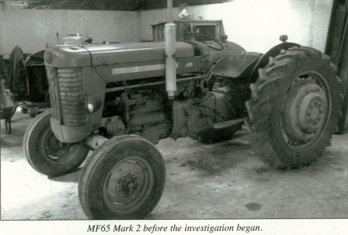
One of the most common complaints about the four cylinder diesel engines of the Ferguson FE 35 (later MF 35) from 1956-59 is that of its poor starting characteristics. This article examines this phenomenon with reference to some Service Bulletins issued to dealers in the period from 1957 to 1959.
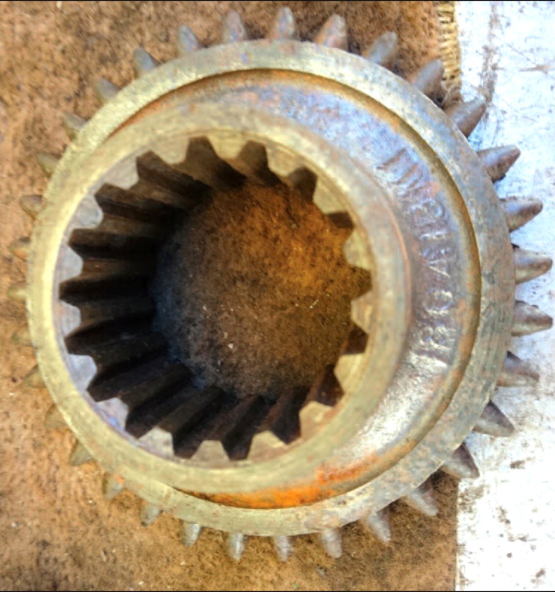
Briefly, the 23C engine was of an indirect injection type with Ricardo Comet combustion chambers and Pintaux injectors, which have an auxiliary spray hole to assist with starting. Dry liners were fitted with aluminium alloy pistons, and were graded ‘F’, ‘G’ and ‘H’. It was, and still is when overhauling, important to match assemblies strictly as there is a variation in size between the three grades. Both Automotive Engineering Co and Wellworthy makes of pistons were used. There was provision for five piston rings to be fitted, four above the gudgeon pin and one below. However in practice only four were fitted (with the option of using a fifth later) though as will be seen from the bulletins, the piston rings were to be one of the main areas of concern in trying to overcome the problems of poor starting in this engine.

Those who are contemplating overhaul of this engine are strongly advised to consult closely the details in the 35 tractor service manual (available through the Ferguson Club and from Massey Ferguson) before dismantling or to seek good advice from engineers who are experienced with this type of engine. Also the I&T shop service manual No MF14 is a good source of information .
The following Ferguson and Massey Ferguson Service Information Bulletins serve to illustrate the problems associated with piston rings in this engine. As early as August 1957 a change of type of the Oil Control ring was made. At this time all rings were fitted above the gudgeon pin, being four in all. The first in this series of bulletins reads thus:
Service Bullletin: Issue No 56(57) Home 55(57) Export 45( 57) Industrial – 5th August 1957
FE 35 TRACTOR
C DIESEL ENGINE
OIL CONTROL RINGS
Advice
In the interest of standardisation it has been decided to discontinue the fitting In production of the ‘Cygflex” ring as an alternative to the “Duaflex” type and with effect from Engine No SJ. 19039 . E both BHB and Well worthy type pistons embody the “Duaflex’ exclusively as the oil control ring. Furthermore it is strongly recommended that this policy is followed in service.
About a year later the following bulletin was issued after complaints of bad starting during the winter of 1957-58. As can be seen, further investigation was made into the Oil Control ring and its effect of excessive oil control causing oil starvation to the compression rings above, and therefore excessive wear and poor compression.
Service Bulletin: Issue No 74(58) – 16th July 1958
MF 35 TRACTOR
C DIESEL ENGINE CYLINDER LINER & PISTON ASSEMBLIES
Situation
Reports were received during last winter that several cases of difficult starting were not cured until pistons and liners had been renewed .
Advice
Assemblies were returned. claiming Warranty in most instances. with allegations of piston and liner wear and grooving of the liners. but examination revealed little or no significant wear and grooving rarely of any depth. Compression ring gaps were. however. found excessive_
The conclusion was drawn that excessive oil control was being exercised by the oil control ring. causing starvation of the compression rings. which resulted in peripheral wear and wide ring gaps.
As advised in Service Information No 56(57) Home 45( 5 7) Industrial. the fitting of oil control rings alternative to the Duaflex has been discontinued for some time. and furthermore. with effect from Engine Number SJ _ 63713. ED. the wall pressure of the Duaflex ring has been decreased to ensure that the oil control is not too severe.
Service Procedures
It is recommended that the low load Duaflex rings (Part Number 826 067 M1) are always used in a new liner. If however the liners have been in service and particularly if oil consumption is in question. the original Duaflex rings (Part Number 1851 045 M1) should be used.
Yet again. after another winter (of discontent?) and another year passed by, more thought was put to the problem of piston rings. It is interesting to note the comments below that fitting a (fifth) ring below the gudgeon pin is NOT recommended at this point in time. Note also the comments on the fitting of spurious ring sets. including a fifth ring. and the use of non-genuine spares. The following bulletin is dated 18th August 1959:
Service Bulletin: Issue No 116(59) – 18th August 1959
FE-35 TRACTOR
C DIESEL ENGINE PISTON RINGS
Advice
A new piston ring set has been Introduced in production as follows.
Piston Ring Description – Top Compression Inlaid Chrome
2nd & 3rd Compression – 11/2° Taper faced
Oil Scraper – Drilled & Grooved (fitted above the gudgeon pin)
All these rings are in material code DTD 485.
Incorporation
Introduction of this change was staggered. taper faced compression rings being introduced separately from SJ. 104912. E to SJ. 105531 . E and SJ. 105663. E and future: the full set from SJ. 112352 _ E .
Service
Advanced field testing has indicated that these rings can be used for service in liners which have worn up to .006″ (0.1524 mm). fitting a ring below the gudgeon pin is not recommended .
Spurious Ring Sets
It has been brought to our notice that on a number of occasions ring sets have been used which are not genuine spares. some of these in fact include a ring below the gudgeon pin _ The results have proved costly and we warn you against experimenting in this manner.
However by November of the same year (1959) yet further investigation had been done and some revision was advised to the previous bulletin in August 1959. Here again the issue of the fifth ring below the gudgeon pin surfaces. and by this time opinion has changed regarding liners that have worn beyond. 003 inches. The following bulletin makes interesting reading:
Service Bulletin: Issue No 166(59) – 17th November 1959
FE 35 TRACTOR
C DIESEL ENGINE
PISTON RINGS – SERVICE (Service Information 116(59) also refers)
Advice
Following further investigation into the piston ring arrangements for service in Service Information 116(59), some revision to these instructions is detailed below.
Service
For liner wear UP to .003· 1.076 mml maximum, it is recommended that the present production ring arrangement, as detailed in Service Information 116(59), be fllted.
For liner wear between .003· ( .076 mm) and .006″ ( .152 mm) it is recommended that the present production ring arrangement and an additional drilled and grooved scraper ring (Part Number 829 732 M1) be fitted below the Gudgeon Pin.
Did all this cure the perennial problems of the 23C engine? In some case perhaps, in others perhaps not, depending on usage. maintenance. whether or not modifications were or were not done and general operator care. By September of 1959 the Standard Motor Company had been purchased by Massey Ferguson and substantial changes were under way quite soon. The MF 35 had a new engine fitted in late 1959 in the form of the three cylinder 3A-152 Perkins unit which was to seal the success of the MF 35 for the rest of its production life (and that of its successor the 135 and other derivatives of that series). Problems of this model were soon to become a thing of the past. However for those users who still operated the old four cylinder 35s the problems were to continue. Yet another service information bulletin has surfaced which makes interesting reading in hindsight. This apertains to the fitting of a starting aid which introduces officially. perhaps for the first time, the use of ETHER into the system for rapid starting. This following bulletin is dated yet another year later,
Service Bulletin: – 12th August 1960.
FE 35 TRACTOR
C DIESEL ENGINE START PILOT
Quite a number of distributors and dealers have for some time been asking us to consider making a Kigass conversion kit available for the earlier 23C diesel engine installed in the FE-35 tractor. Investigations into this possibility prove that it Is impractical and uneconomical, therefore as an alternative and as a result of extended and exhaustive research into starting problems associated with the 23C Standard engine brought to our atlention particularly during winter months, we are pleased to announce that a suitable and economical starting aid has been approved which will, sUbject to reasonable demand from distributors and dealers, be available witnin the next two to three months.
The starting aid known as Start Pilot is a unit consisting of a single acting pump which accommodates a capsule containing approximately 75% ether and 25% base fluid. A metal capillary tube from the pump leads to the rubber hose between the air cleaner and the inlet manifold for connection to a nozzle which is supplied to accommodate the pipe .
In addition a spring loaded ‘push button switch’ is included to accommodate the thermostart connectiofn which, with the Start Pilot. must be transferred to the ‘push button switch’ from its present position on the starter switch.
Tests have proved that. provided the engine is in a reasonable mechanical condition, the electrical equipment is effective and the starter motor capable of producing 110/120 rpm engine speed, excellent results can be achieved even at minus 5 deg centigrade. With the Pilot Start fitled the thermostart is by-passed, but it should not be removed because repositioning of the cable from the push butlon to the starter switch will make the thermostart operative for use in moderate temperatures.
This equipment, which can be fitled in approximately one hour, is invaluable when the ambient temperature is sufficiently low to prevent effective starting by the orthodox method.
Fitting and operating instructions will be made available.
The price is dependant on demand which, if of sufficient volume, will. we anticipate, enable us to supply each Start Pilot Kit at £5 nett.
It is most important to us to have some indication of requirements so that we may arrange production and price accordingly. therefore your assistance in completing the attached form and returning it to us as quickly as possible will be greatly appreciated .
Does any member have a four cylinder 35 with the remains of the Start Pilot device still attached? Or does anyone recall what it looked like or how effective it was? It must have been about this period that aerosol cans of ether starting aid came onto the market and became an ever present item in the tool box of the old 35s . The smell of ether almost comes to the nostrils as one writes this treatise. Nostalgia apart. it is hoped that the above service information on the details and intricacies of piston ring configurations on the 23C diesel engines will be of benefit to anyone considering a full restoration of an early FE or MF 35 tractor. Again it is emphasised that careful study of the 35 service manual as mentioned earlier should be considered .
@W J Baber 1991
Further to this article, Mr Bob Stoddart of Fewsters Lid sent in the following information:
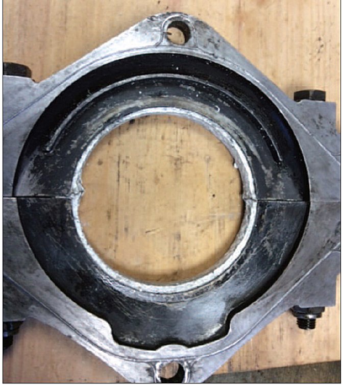
This modication proved extremely successful in overcoming the poor starting problems experienced with the 23C engine fitted to the FE-35/MF-35 tractor. The modication involves opening up the combustion chamber port. thus allowing a certain amount of direct injection to take place. Unfortunately the exact dimensions cannot be remembered. however the modification could still be carried out from memory.
A rough sketch is given hereunder:

The shape was marked out with a scribing tool. a centre punch was used to break away the material just inside the scribe marks. The finished shape was achieved using a small three cornered file. port edges were chamfered.
We will continue this survey of 23C starting problems and equipment in another issue of the Newsletter.
Published in Journal No, 17A, Vol.5 No.3 Spring 1992