
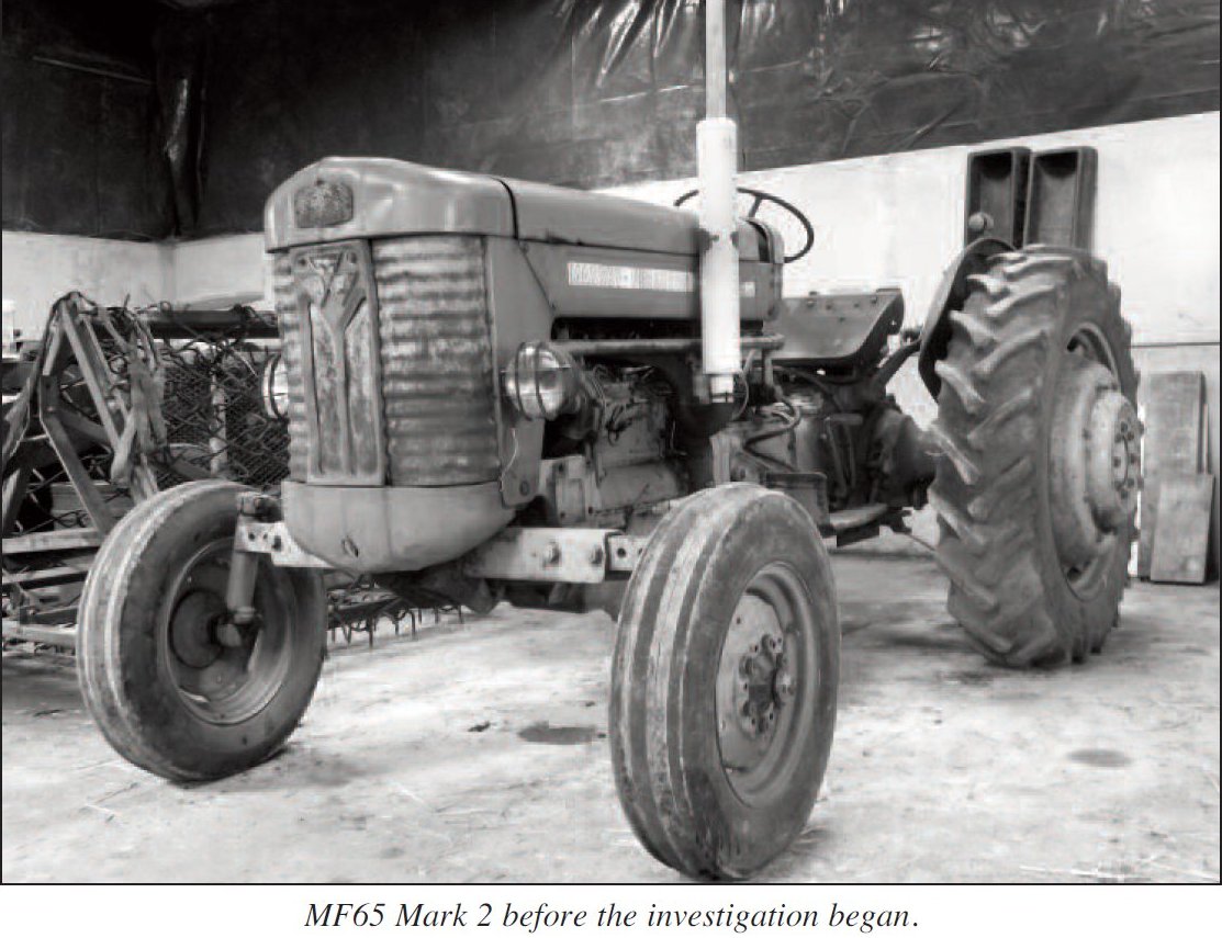
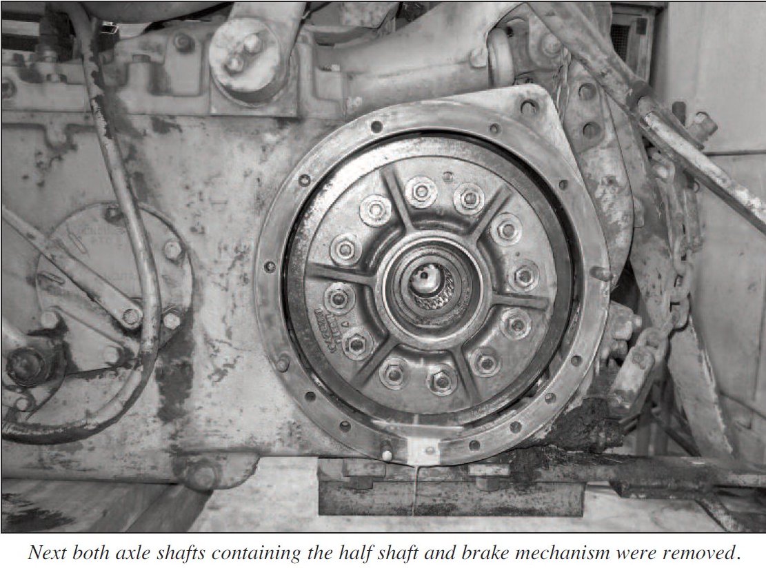
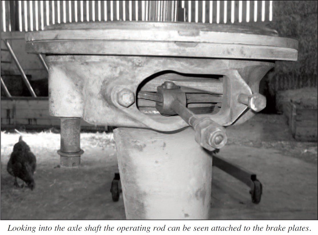
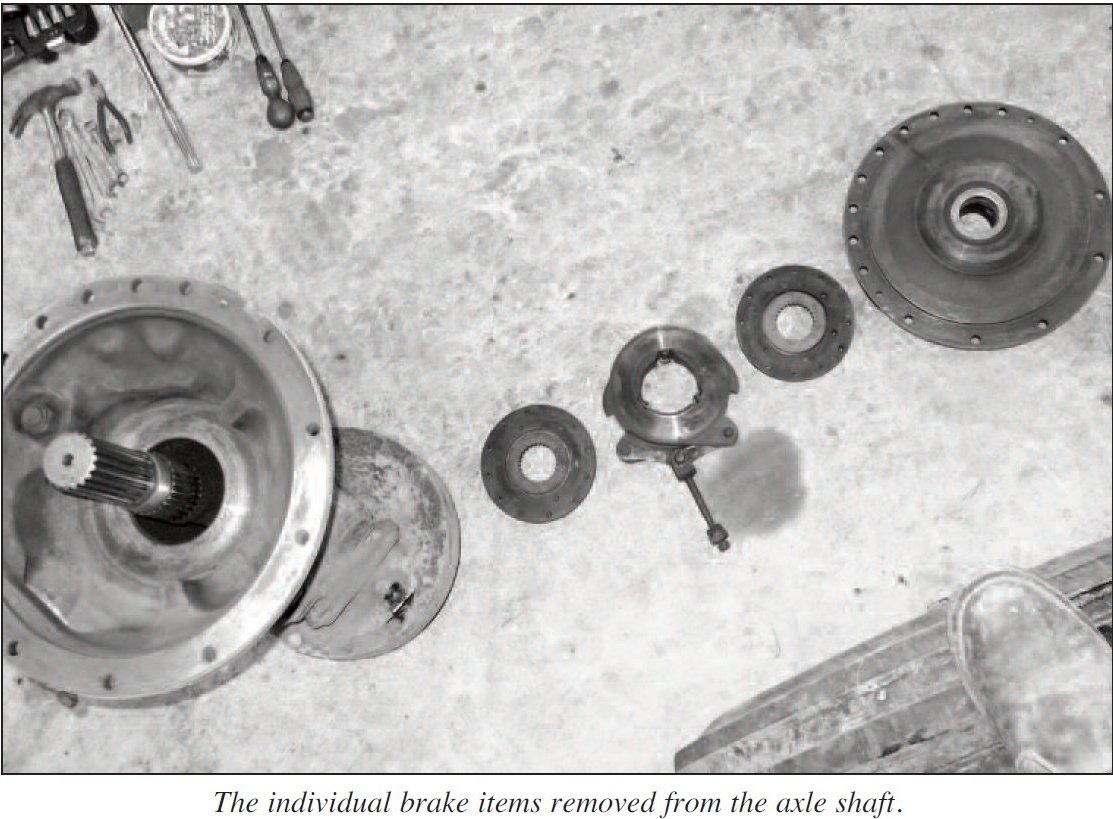
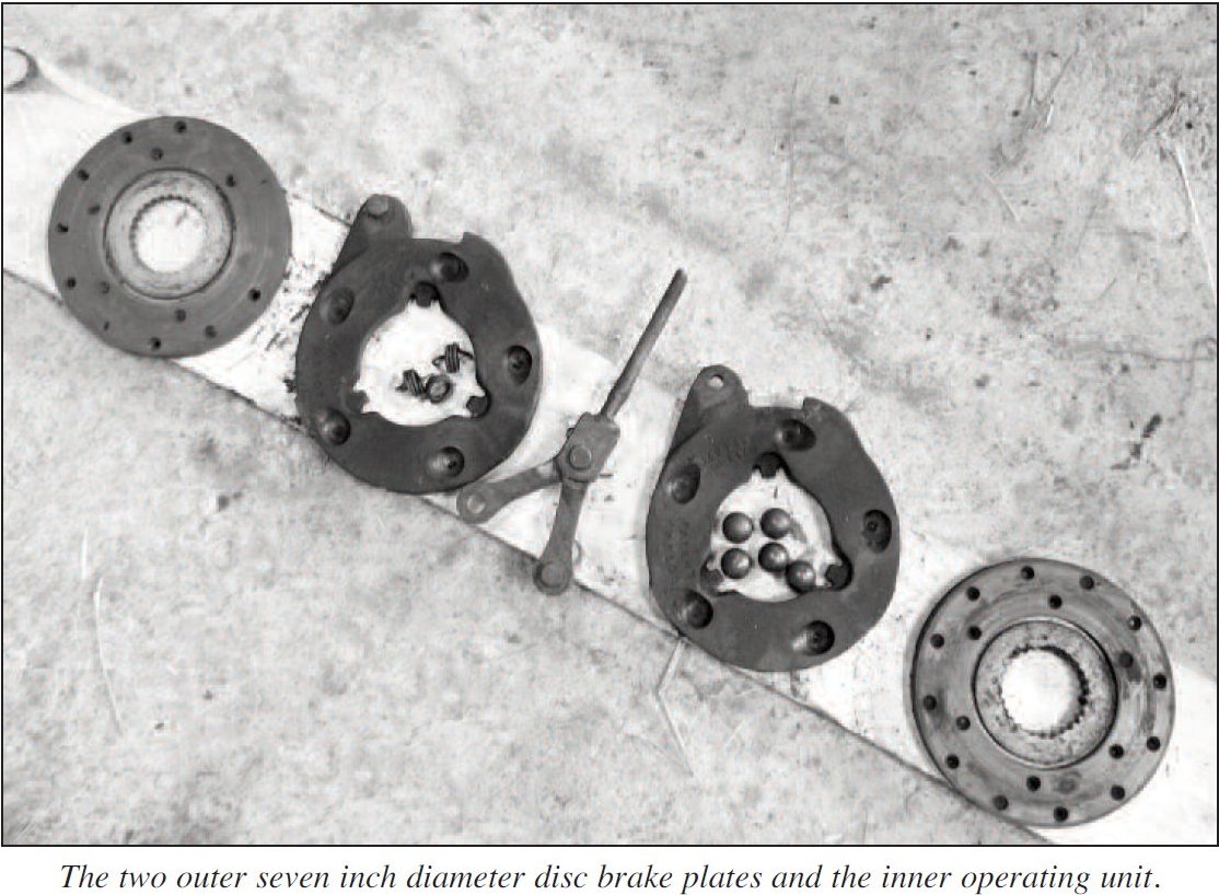
From the day I purchased my MF65 MkII the brakes have been appalling, making the most horrendous binding noise and uncontrollable lock up. It was time to investigate the cause and to get the MF65 brakes operating correctly.
Published in Journal No.83 Summer 2016 : Tim Hanson / Barry Moody
Author Archives: Peter
Fitting Rings to a MF135 AD/152 5·Ring Piston 🔑
Starting with piston rings one, two and five, use one of the rings to measure the cylinder bore top, middle and bottom to check the bore is parallel, use one of the pistons to keep the ring square in the bore. All three measurement should be close to each other, this lets you use the top of the bore to check the gap on the rings.

Using one of the pistons to push the ring into the bore keeping the ring square.
The ring gap for most older engines is between 0.003 to 0.004 thousandth of an inch per inch of bore, on a 3.6″ bore you would be looking for between 0.011″ and 0.015″ clearance. Please check engine manual for engine data against specific engine model.
Measuring ring gap with a feeler gauge.
The thinner corded rings should be checked in the same way, for grooves three and four. If any of the rings require gapping, grip the ring gently in a small smooth jawed vice, then with a fine file remove a small amount of metal, keep checking the gap after each stroke of the file.

Gapping the rings using a small vice.
The small cord rings are fitted in pairs, one up and one down to give a V shape. To check how this works if you squeeze the ring, the ends will either go up or down, then you require one up and one down ring to go together onto the piston.
Lightly squeezing one of the cord rings
Groove three has four cord rings fitted in two pairs, one down one up and one down one np, when fitted correctly this should give a small gap between the two rings.
The arrow points to the small gap.
Before fitting the pistons into the engine, start spacing the rings and around the piston, the most important ring is the top ring, keep the gap away from the thrust side of the cylinder bore, the rest of the ring gaps can be spaced round the piston, but not in line with the piston gudgeon pin.
Groove two has a standard cast ring, top groove has a chrome plated ring. The saying goes, cast liner chrome top ring, chrome liner cast top ring.

The chrome ring stands out from the others.
The thrust side of the cylinder bore on this engine is the opposite side, to the fuel pump and injectors.
Piston ring kits fro different manu¬facturers will contain different types of rings, this is just one type illustrated above.
Published in Journal No.105 Summer 2023 : Sandy Donald
Brakes Reline-Repair-Adjust: Ferguson & MF 🔑
Are your Ferguson or 35 brakes in good working order? Many of the older tractors suffer from poor brakes for a variety of reasons. The old drum brakes work very well when everything, including linings and drums, linkage etc are in reasonable order and correctly adjusted.
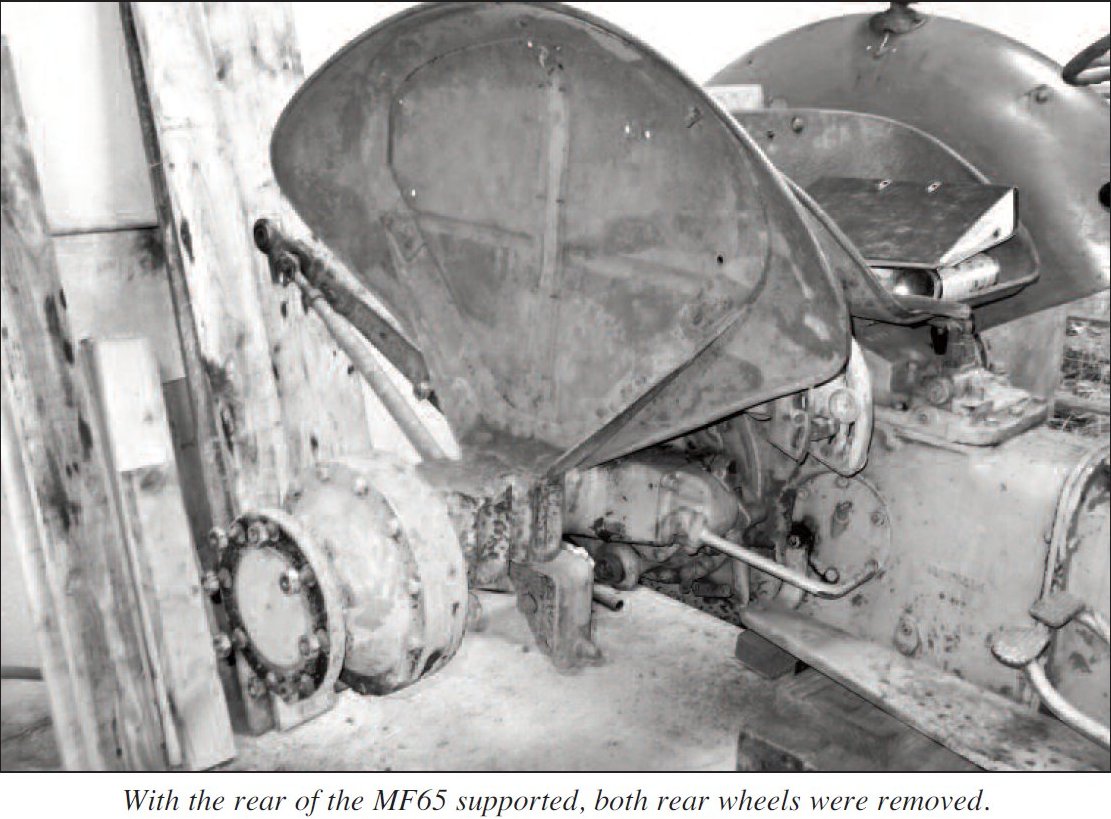
To facilitate re-lining or repairing we make the tractor safe with suitable axle stands. Now to remove the brake drums.
These are held on by two screws which may be tight and awkward to move. Try tapping around the screw head with a hammer or as a last resort try some heat. With the two screws removed, the brake drum can be removed but again after years of rust etc we may find it stuck fast. To help removal of the brake drum, two threaded holes are provided on the bake drum. (see photo 1). Screwing two bolts into these holes should pull off the brake drum. The holes are 7/16 UNC thread, the same as the hydraulic top cover bolts so we can borrow two top cover bolts.

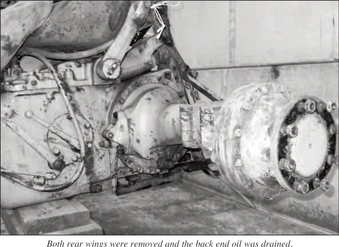
With the brake drum removed we can inspect the general condition of the brake linings, return springs, brake drum etc. The brake linings are held on to the back plate by small springs on 35 models and by a nut and large flat washer on the grey Fergies. Before removing these it is better to remove the strong return springs first.
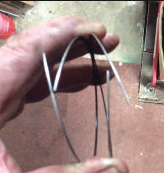
To remove these strong springs make a wire loop – welding wire is ideal. Connect loop to the end of the spring using a bar through the loop, lift the spring from its anchor (see photo 2).

The small springs can now be removed and the brake shoes complete with adjuster etc removed. The linings should be dry and have a reasonable amount of actual lining left on them (min 3mm) at the thinnest point. If they are contaminated with oil, grease, slurry etc they will need replacing Lining and rivet do-it-yourself kits are very reasonable on price but not at all easy to do. We find having your old shoes re-lined with a soft bonded lining gets the best results. Brake drums should be bright and smooth with no scours or grooves. Adjusters and moving parts need to be free and coated with copper slip grease before reassembly.
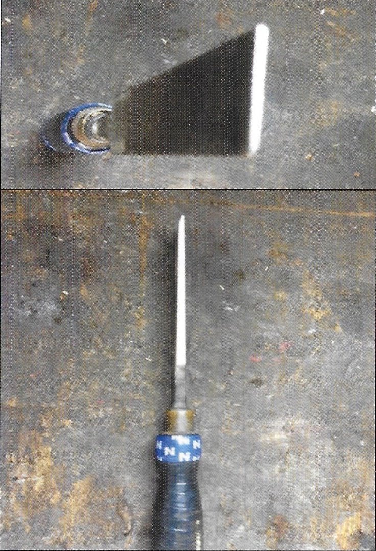
Assembly of the brake shoes is basically a reversal of the disassembly procedure. With the brake drum re-fitted it is time to adjust the brakes, this is accomplished by turning a star wheel, adjuster with a screwdriver (see photo 3) through the back plate.

It is a good idea to have a practice of this procedure before fitting the brake drum. Adjust the brakes up as tight as possible and back off the adjuster until the drum just turns. Next, drive the tractor and use the brakes before finally adjusting again and balancing, making sure the wheels pull-up evenly.
Published in Journal No.58 Spring 2008 Jim Hall
Homemade Brake Adjusting Tool 🔑
Home made Brake Adjusting Tool
 For tractors with slots in the backplate for adjusting the brake shoes Sandy Donald
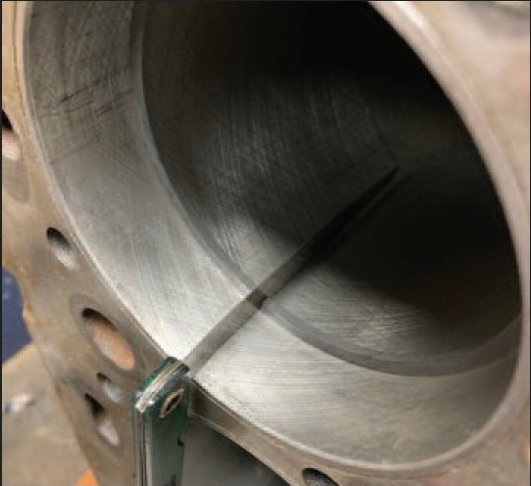
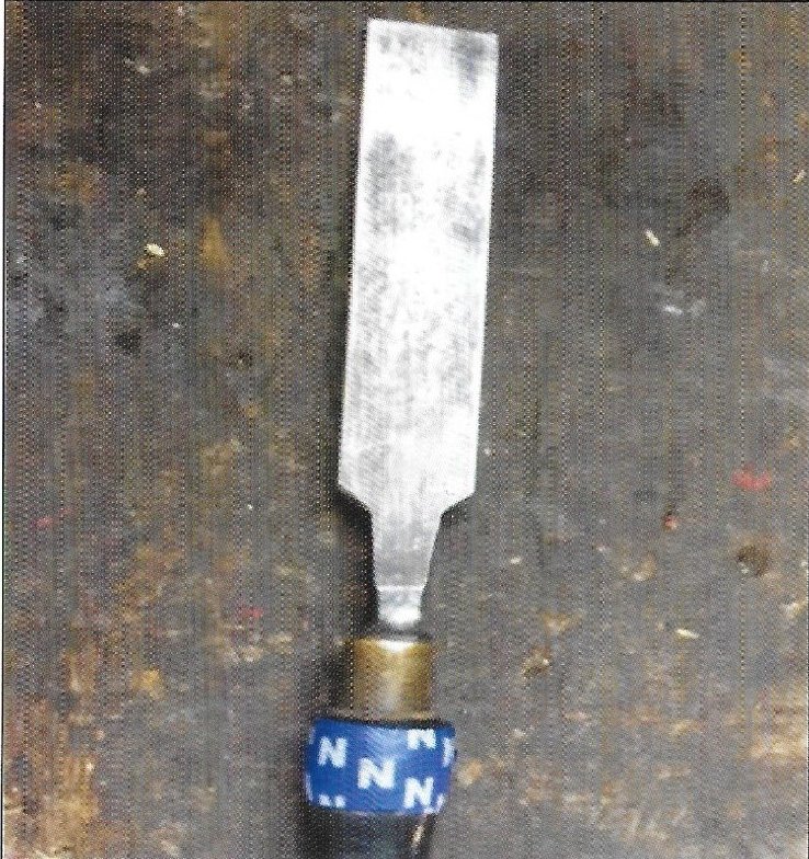
Take an old 1″ or 25mm wood chisel and make it into a blunt chisel about l/16″ or 1.5mm flat on the end. You can rest the chisel on the bottom of the slot and line it up with the star wheel inside the drum, lot easier than using a screwdriver.
Published in JournaL 106, Autumn 2023, Sandy Donald
Rear Hub Seals and Bearings (TE & MF)🔑
Restoration· Rear Hub Seals and Bearings
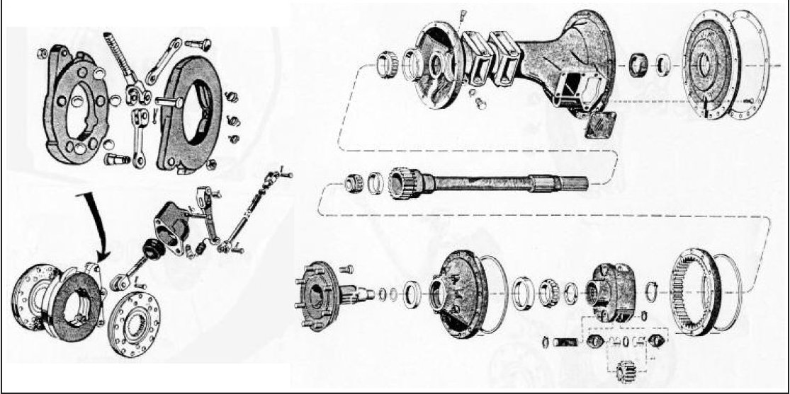
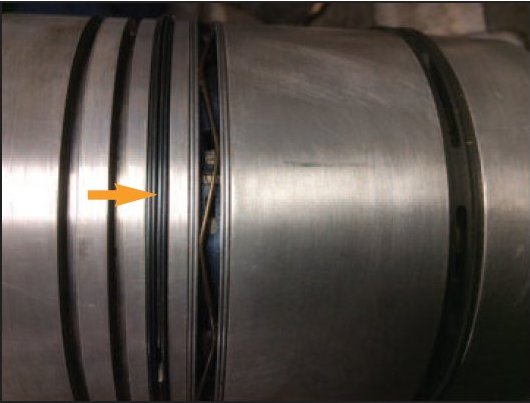
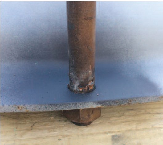
Ferguson TE20s and 35 tractors can sometimes suffer from poor braking due to oil contamination of the brake linings. This is due to the half shaft oil seal leaking transmission oil into the brake drums. In early Fergusons, only one seal was used behind the main half shaft bearing. In later tractors, TEFs and all 35s, 135s etc., two seals were employed one behind the main half shaft bearing and another in the end of the trumpet housings (see photo below). To replace the oil seals and or the half shaft bearings, we must firstly remove the rear wheel making sure that we make the tractor safe with axle stands etc. With the wheel removed we now need to remove the brake drum followed by the half shaft assembly by removing the nuts behind the brake back plate (see Journal No.58). With the half shaft removed we can now see the aforementioned inner seal (later tractors) inside the trumpet housing. As the half shaft is removed, spacer shims from between the trumpet housing and the back plate may drop out.


With the half shaft removed we can now see the bearing. This is held in place by a collar – which is a shrink fit and can only be removed by cutting or splitting the collar. This can be achieved by firstly drilling vertically down the collar and then splitting with a sharp chisel (see photos above).
With the half shaft collar removed we can now pull off the bearing housing. If the bearing is being replaced, we can cut the old unit off with oxyacetylene. To save the bearing a special ‘puller’ has to be used (see photo opposite) showing homemade puller. With the hub and bearing removed, we can now replace the outer oil seal. bearing etc. A new shrink on collar must always be used as this holds the half shaft into the trumpet housing. The collar is fitted by heating the collar until cherry red in colour and then dropping onto half shaft behind the bearing. When re-fitting the half shaft: replace the shims from between the brake back plate and trumpet housing to achieve a small axle end float of around 005″ .
I would be only too pleased to help any Club members with the described procedures. Please feel free to ring me (number redacted, available to club members in Journal 66, Members Area).
Published in Journal No.66 Winter 2011/12 Jim Hall
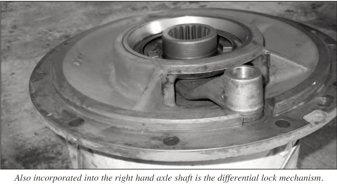
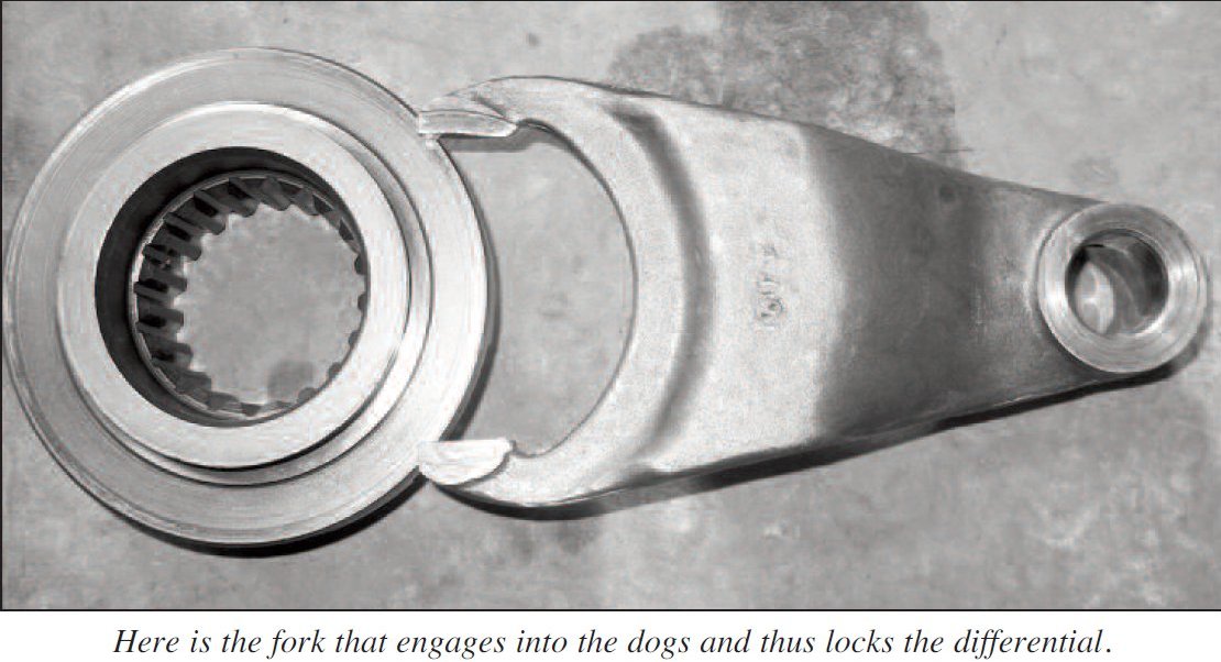
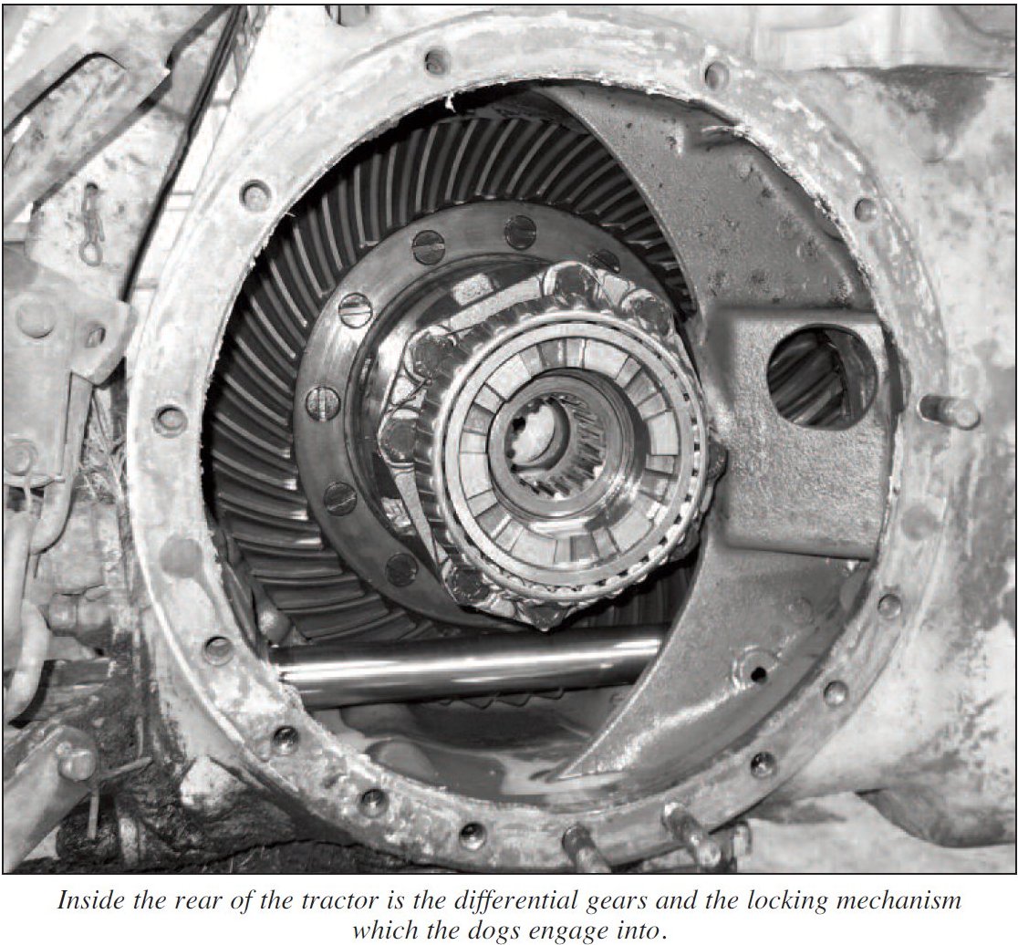
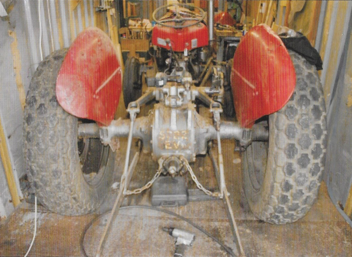
French Built MF188 Differences 🔑
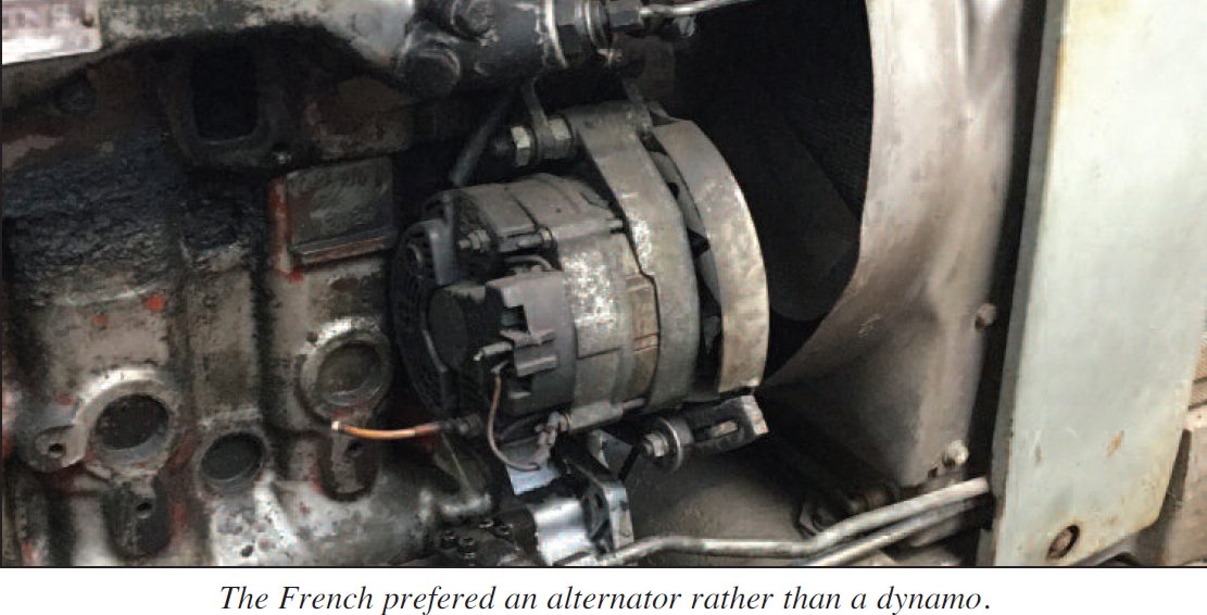
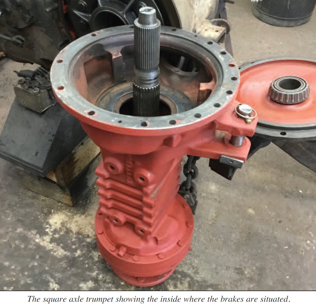
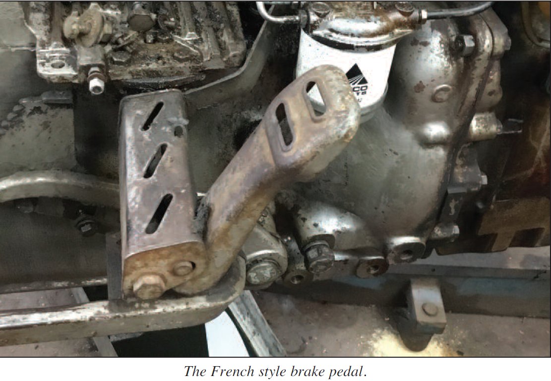
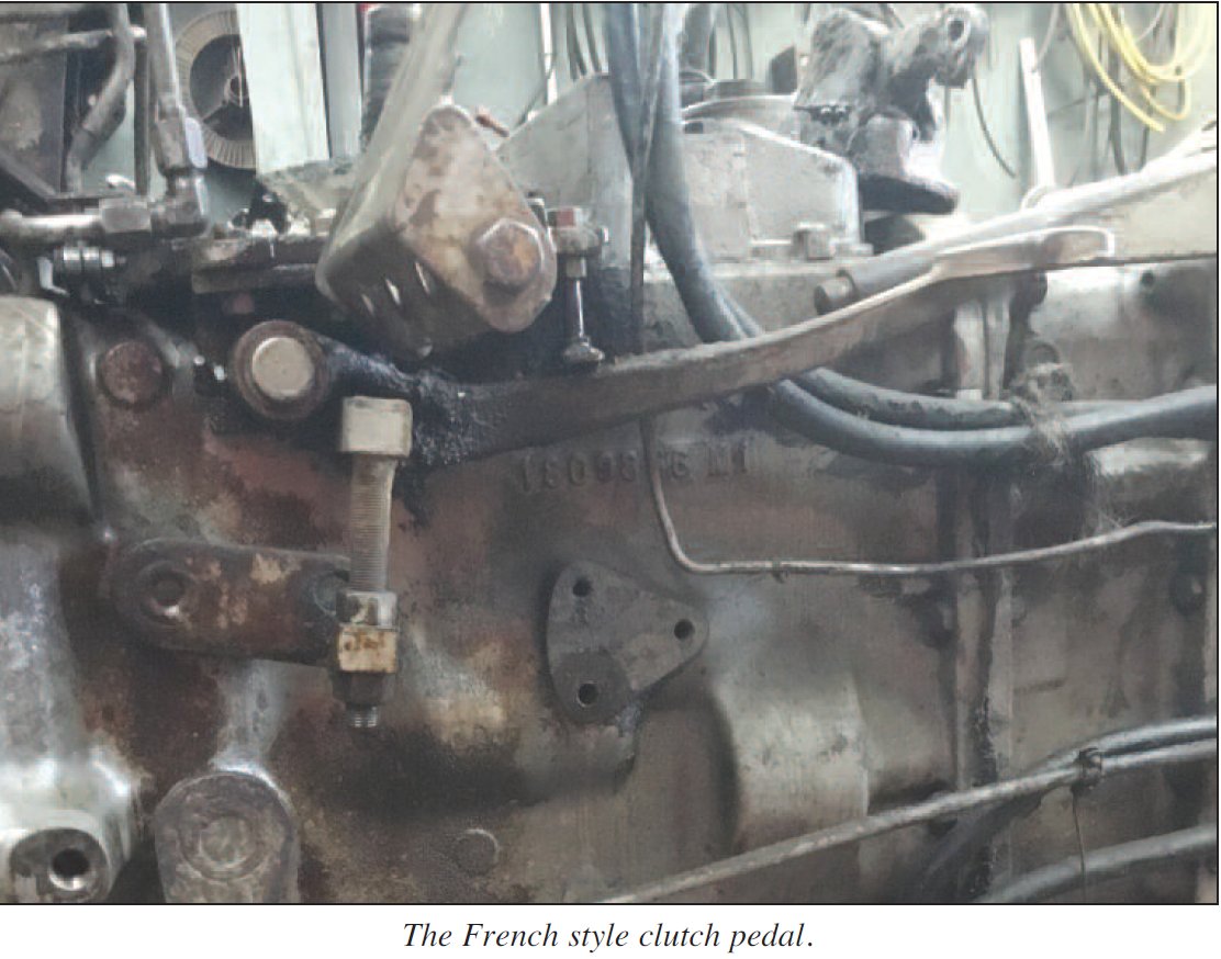
This French built MF188 tractor is quite au unusual model in this country and is different in many ways to the Coventry built MF188. The 4WD axle would appear to be the same as the first 590 4WD’s with the large front hubs that protrude out past the wheel. The clutch pedal and linkage is completely different, but probably better than the British one which always seemed to be very high. Tbe electrics use an alternator rather than a dynamo, gauges are French with an extra pressure gauge for the low pressure hydraulic system feeding the multi power, IPTO and 4WD clutch. Tbe back end has square axle trumpets, but dry brakes using 8 1/2 discs, as used on early 595’s and 1200’s.


Published in Journal No. 88 Spring 2018 : Jim Hall (Technical Team)
Rear Tyre Removal 🔑
Removal of a perished rear tractor tyre
My way of removing a perished rear tractor tyre from its rim and then replace with new rnbber. In this article I describe my way of removing a tyre which has reached the end of its life and how I would fit a new tyre.
Firstly you need to assemble all necessary ‘equipment’ which is a sharp robust knife about 8″ to 10″ long and with a substantial handle (mine is a Lidl £2.99 special), a bottle of washing up liquid, a stout pair of gloves, a 4.5″ angle grinder with new thin cut-off disc fitted and a pair of safety goggles and to fit the tyre a pair of long tyre levers. Sometimes I remove the centre to reduce weight.
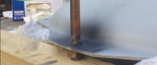
With the wheel/tyre assembly lying on the ground and starting where the lyre has split, cut the sidewall about 3″ from the rim all the way round, lubricating the cutting
area generously as you go. (See photo 1). This is not as difficult as you might think and took me under 5 minutes for one side.

Turn the tyre over and repeat the operation. You should now have the tread separate from the sidewalls and free of the wheel. Remove this from the wheel. Remove the inner tube by just cutting it free.
Now cut into the sidewall towards the rim to form a notch about 2″ wide tapering to a V. (See photo 2).
 Remove this piece of rnbber. Repeat on the other side. It doesn’t matter where it is, it is to give you access to the steel reinforcing bead that sits against the rim of the wheel. I now position the wheel so that one side is raised about 12″ to 18″ off the ground. With your safety goggles on, take your angle grinder and working from the inside of the wheel, cut into the tyre at
the bottom of the notch into the steel reinforcing, taking care not to damage the rim. When you have cut through the steel the sidewall will spring off the rim and is easily removed. Repeat on the other side. Job done!
The whole operation took me less than 30 minutes.
I do actually cut the tread portion into two for ease of handling. (See photo 3).
 Using the same technique as for the sidewall I work between the treads and end up with much easier pieces to load into my car to take to my garage for disposal. Be prepared, you may have to pay up to £25 for disposal, but, please do not fly-tip.
Now the rim can be refurbished, and I’m sure you will all know how and what to do.
Now to fit the tyre. With your newly painted rim on a soft surface, like a piece of carpet, place the lyre over the rim. Push one side of the lower bead into the well of the rim and now walk around the tyre, most of it will go over the outer rim and the rest can usually be persuaded with a bit of washing up liquid or tyre soap and kicking or hitting with a hide hammer or with the levers.
The inner tube is now fitted and I use one of those key like devices which removes the core or improves the inner and outer threads and screw onto the valve you have poked through its hole. This ensures it doesn’t slide back inside the tyre. Work the tube quietly into the rim and when home inflate slightly, with the valve core removed, to remove any creases. I now raise the lower part of the tyre onto three pieces of wood each about 3″ thick in a crescent shape in the area opposite the valve. This will enable the bead to go into the well of the rim. Now start working the outer bead of the tyre over the rim. You should be able to work at least half into position by just walking on it. Now you will have to resort to the washing up liquid and use of the tyre levers. Be very careful not to nip the inner tube with the levers or you will have to repair a puncture before you start! Work the levers from either side of the rim making sure the fitted part of the tyre is down in the well of the rim. Work by taking small bites of tyre to move over the rim and eventually your efforts will be rewarded. Now, carefully holding the shank of the valve so it doesn’t pop back inside, inflate the tyre to 13 psi. Inspect to ensure the bead is evenly down into the rim both sides. Happy motoring.
Published in Journal No. 87 Winter 2017/18 : ‘Tractor Grandpa’
A Pressing Matter …….. Not !
When I bought my MF35, it came with turf tyres which, apart from them standing flat for the best part of twelve years, I didn’t particularly want and so, early on in the restoration process, I decided to replace them with standard rear tyres.
Now I’d had trouble with front tyres previously on my TE20, trouble breaking the seal that is. I tried all kinds of things like running my car onto the tyre while it was flat on the ground, smacking it with a sledgehammer, various crow bars and the like and finally I thought of my vice. Luckily, I have an old blacksmiths vice with plenty of room between the jaws and the screw, enough in fact to allow room for the tyre when the wheel rim is resting on the jaws. I used a foot square of ¾” scrap ply between the back jaw and the rim, to spread the weight, and with the front jaw as close to the rim as possible, a good squeeze from the vice broke the seal, it was then turned round and the process repeated, the tyre was then removed with the aid of my lump hammer and a couple of crowbars (some of you may have proper tyre levers!)
That was relatively simple on the front tyres, but the rear ones were a different kettle of fish!
Some years ago, I’d had to replace one of the rear tyres on myoId TE20 (it never had much tread when I bought the tractor some 38 years ago) so I set to, without success I might add, trying to get the thing off. I eventually gave up and resorted to the ‘professionals’ at the local tyre company; well, they did get it off and they supplied a new one but, in the process, they totally mullered the rim; both sides. I wasn’t best pleased, but they did give me a 10% discount!
Then, of course, I had a beat-up rim, albeit complete with tyre, but as it was only a few hours old and covered in tyre-fitter’s gunk, it came off easily; some hours later, with the aid of both sledge and lump hammers, I got them back to something like normal and ground off the sharp edges that would almost certainly have cut the side walls.
With that experience behind me, I decided not to go that way again.
A while ago, I joined the Ferguson Club from whence I’d received some sound advice on other matters, so I gave John Selley a call. It transpired that he’d come across the same problem but he, not wanting to save the old tyres, resorted to various knives and an angle grinder in the removal of same! As my turf-tyres had life left in them, I wanted to get them off relatively undamaged if possible, hence the call to John.
He knew a man who knew a man who had a hydraulic press that would easily break the seal if we could get the wheel in it; we couldn’t, but he directed us to a farmer a way down the road who “might be able to help.” Now, said farm sported a newly opened farm shop and cafe staffed by an extremely attractive young lady who plied us with coffee and sticky buns whilst waiting for the farmer to appear. He’d “never had that problem” but thought the local agricultural dealers might be able to help. By this time though, I was lost as John was driving, so I have no recollection of where or who they were (John doesn’t even remember the trip) which is a great shame as I can’t directly credit the chap who gave me the solution to the problem. (If you are that man and happen to read this, please let me know and I’ll give credit where credit’s due.)
Anyhow, John met an old mate outside and whilst he was chatting I went in search of a press. In the workshop I met a chap to whom I explained the problem and “did they have a press?”
“You don’t need all that junk mate” he explained “you just need three old bits of old angle iron, a lump hammer and room to swing it! Look here” he said gesticulating to a huge Fendt tractor “it’s so simple; if I wanted to change those tyres, I wouldn’t even bother taking the wheels off.”
I can best illustrate his method with the photographs I took as I tried it out at home.
I firstly cut three lumps of 2″ angle iron about 4″ long and de-burred all the edges then, as my wheels were already off, I worked on the floor.
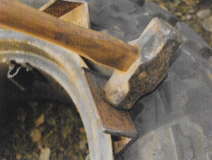
Method as explained to me:-
“Firstly, thump a cold chisel in between the tyre and the rim to give the angle a start, then knock in the angle, one corner first. `
When that has a start, smack the angle home as far as it will go.
 Drive angle in in direction shown.
 Drive in from the side.
Move round the tyre a few inches and repeat the process with the remaining two angles. By the time they’ve all been beaten home the tyre will be free of the rim on that section and the rest can be freed off using just the hammer.”
I have to say I was sceptical when he first explained it to me and though I didn’t say anything, I thought he was having me on, but all I can say is “try it!” it worked for me!
It’s always good when the simple solution works and it’s not just a fluke; I’ve now used it on four rear wheels, the ones illustrated and both on my TE 20 (I managed to puncture both those on the same day) but as it is quite literally a ten minute job to get the tyres off with this method, I wasn’t too long off the road.
I did try leaving the wheels on but found the inner rim seal was impossible to break as there wasn’t the required space to swing the hammer, however, it’s much easier to fit the new tyres (or replace the old ones) with the wheels on the tractor as that enables gravity to lend a hand, an extremely reliable helper and free to boot!
By the way, I got £80 for the old tyres on eBay, much better than carving them up to make flip-flops or starting a bonfire!!
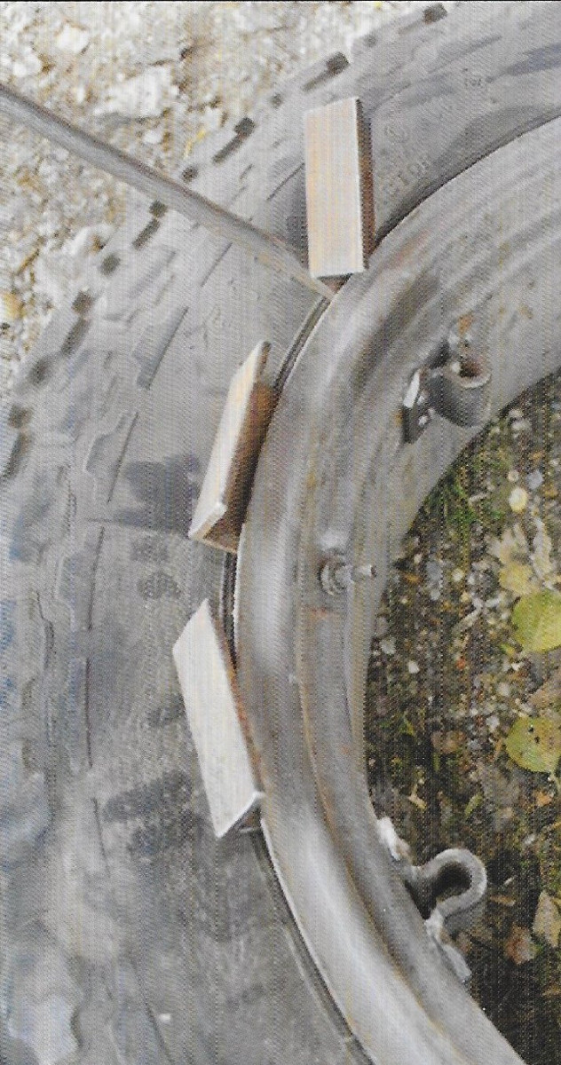 Repeat at intervals round the tyre.
 You can quite clearly see the years of rust.
 Despite stonding flat for twelve years, both innertubes held air when they were pumped up.
 Tyre and rim virually undamaged.
Published in Journal No.99 Autumn 2021, John Lindley
Britool Steering Wheel Puller 🔑
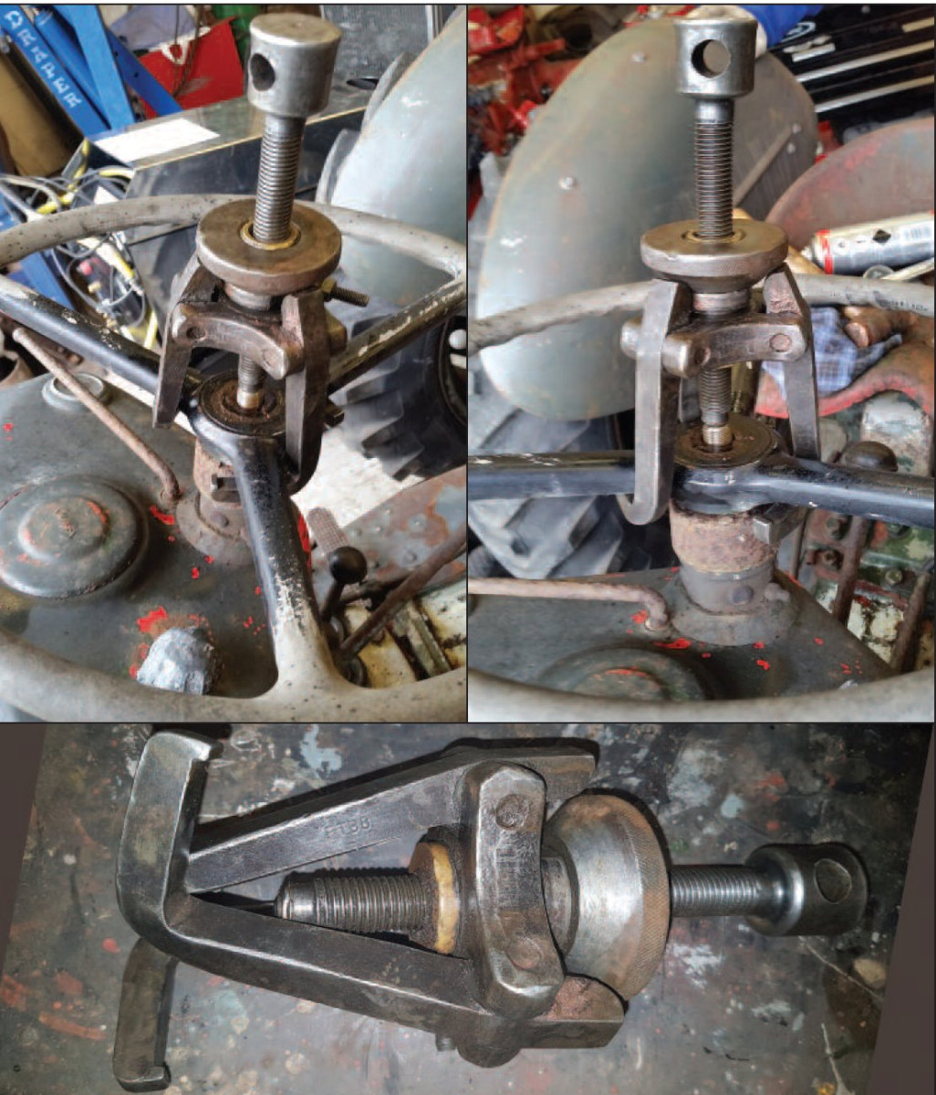
One of my customers got talking about serving his time as an agricultural engineer for a Massey Ferguson dealer. We spoke about special tooling and the steering wheel puller made by Britool. He went away and came back with this fine example of a three legged puller tooling number FTB8.
I got it away on loan with the words ‘bring it back or else, you’re not getting it for keeps’. This was the polite version of his words. I put it to the test and it worked a treat.
Over the years I have destroyed several steering wheels trying to remove them.
Published in Journal No.88 Spring 2018 : Kevin Britton
Repairing Worn Holes 🔑
Hot Repair Tip
If anybody has trouble with a wheel centre that has a worn bolt hole, fit a 15mm copper pipe or aluminium tube through the hole and weld around it, then simply tap the pipe out and buff the weld flat. Simple and easy to repair. If the hole is bigger use same material to take up the desired bolt size.
Published in Journal No.89 Summer 2018 : Willie Brownlie
Gasket Pad for Gasket Making 🔑
This is a very simple project for making an extremely useful pad for punching holes in gaskets being made.
Materials:
One old bearing cup 4″ to 4′;,” diameter, a TE20 differential bearing carrier. A mild steel disc cut from a bit of plate to the bearing cup diameter. A couple of welding rods. Sufficient lead that can be melted and poured into the pad to fill it. Old batteries or fishing line weights are a source for lead. Weld it together and fill with melted lead.
Tools: A hammer and set of bell punches.
There is no need to re-melt the lead when the surface gets cut-marked from the punches, just flatten it with a hammer. I can make gaskets for carburettors to gearbox tops that are indistinguishable from bought or ones. I gave up using a block of wood 45 years ago!

Published in Journal No.53 Summer 2006. Dennis Field