A Silly Mistake and a Tricky Problem on a TEF20
A whiff of QuickStart and brrrrrrrmmmm … She’s off and ready for a day’s work. That’s how it was in the summer of 2016: a 1952 Ferguson TEF20 501692 – absolutely no problems. Then, due to a misfortune that befell its owner she – the tractor – had to be laid up for the winter, snugly under cover with plenty of antifreeze and the diesel tank full to the brim.
Around Christmas time we went to have a look and all seemed well except that there was a mysterious wetness on the ground immediately under the engine. I thought nothing of it, after having checked the radiator fluid and looked for leaks in the cooling system.
Now more or less back on my feet I set off on a sunny morning in early April to recommission the Fergie and prepare for some fieldwork. The first sign of trouble was a totally empty fuel tank. The tractor had been left idle for five months with the fuel tap immediately under the tank turned ON. The leakage – very slight – was traced to the injector pump. A full tank of diesel had gone. Now that you have finished saying ‘Stupid boy’ and other rude things, let’s look at some data.
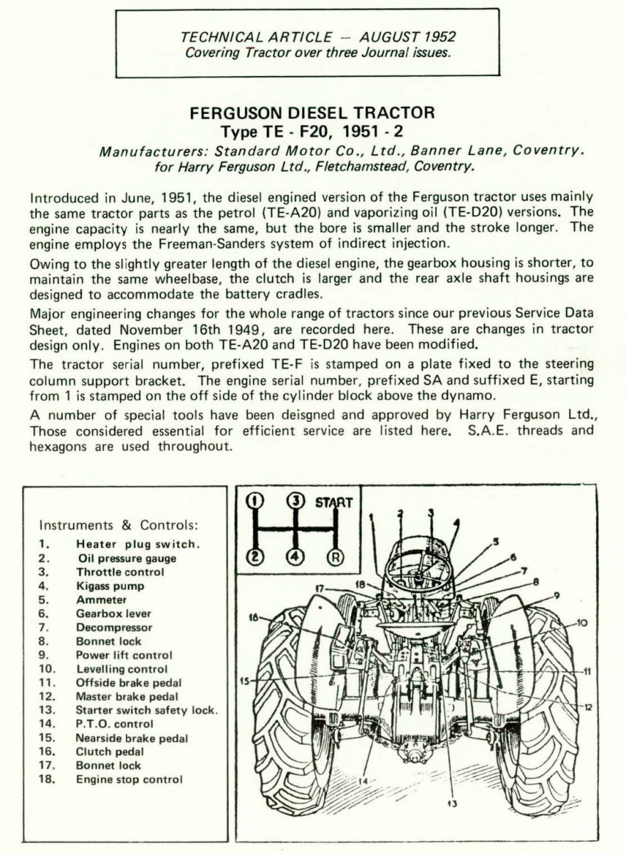
It’s a 1952 TEF without a lift pump. The fuel is gravity fed to the injector pump through a tap and two filter units. The injector pump has a diaphragm and three bleeding points. The diaphragm chamber connects by a pipe to the inlet manifold. There is a throttle linkage point and an engine stop lever.
Now remember: when the tractor was laid up in the autumn of 2016 it was functioning well. I first filled the fuel tank half full of fresh private car grade diesel. I then bled the entire fuel system – tap, number one filter in and out, number two filter in and out, bleeding point on the top/front of the injector pump and then both bleeding points on the side of the pump. All OK. A whiff of EasyStart and nothing! More EasyStart – nothing! More bleeding and more EasyStart and reluctantly the engine started to fire and eventually settled to a fast tickover – much too fast. As soon as I reduced the throttle setting, the engine died. Tried again and this time INCREASED the throttle setting – the engine died. Tried again and cautiously engaged first gear with the engine doing its fast tickover. Eased out the clutch and as soon as the load engaged, the engine died. Tried again and this time killed the engine with the stop lever: and this is important because it tells us immediately that – PHEW … – the rack of the injector pump is not seized. The rack is the shaft that moves forward and back in the pump and regulates the amount of fuel being sent to each injector. It is not uncommon for the rack to seize if the pump is unused for a long period. The engine stop lever pushes the rack all the way backwards and cuts off the fuel to all injectors completely.
This is the point at which all good men start to ask questions. Workshop manual: there isn’t one that covers the fuel system. Enquiries to the Ferguson Club put me in touch with four technical advisers for the Club. All of these did their very best to be helpful and one of them (Jim Hall) was especially encouraging on the basis of personal experience with pump removal and repair. It was Jim who observed that, sadly, most of the first-hand knowledge and understanding of 1950’s systems like the TEF20 injection pump was six feet down! Finding out led me to a really helpful and quite entertaining YouTube movie about stripping and rebuilding the pump (https://www.youtube.com/watch·v=JHMKUAYG_Ng). I recommend it, even if you don’t have a pump. Good watching for a winters evening when there’s nothing on the tele!
The pump basically consists of a rod the rack – with four sets of gear teeth at intervals along its length. Each of these engages with a cog at the base of one of the four injector elements. Move the rod on its long axis and it has the effect of rotating the four cogs of the elements. This changes the amount of diesel that is delivered to each injector. The elements are activated from a camshaft that occupies the base of the pump. The cams push the elements up, driving diesel up and out through the injector. The springs on the elements return them to their original closed position. It’s just like the action of an overhead camshaft system for opening and closing inlet and exhaust valves on a cylinder head.
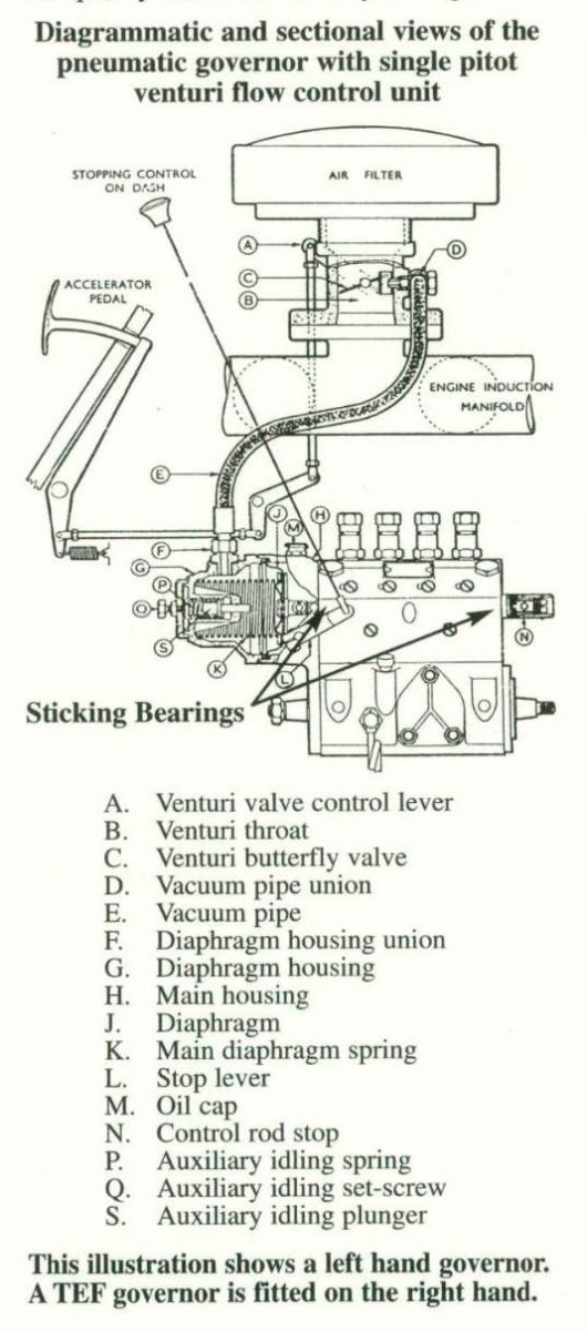
Longitudinal movement of the rack is produced in several ways. Pulling the rack backwards closes all the injector elements and reduces or stops the flow of diesel. The engine stop control pulls the rack all the way back and – stops the engine. Inside the rear portion of the pump there is a diaphragm which is coupled to the back end of the rack on its forward side. The diaphragm chamber is connected by a vacuum pipe to the engine’s inlet manifold. Low pressure in the manifold while the engine is running sucks the diaphragm backwards and so pulls the rack backwards, reducing the flow of diesel and slowing the engine. This arrangement effectively helps to maintain a balance in the amount of fuel being injected and the volume of air being sucked into the cylinders. Behind the diaphragm is a large coil spring which pushes the diaphragm and the rack forwards, counteracting the backwards suction force on the diaphragm. The throttle control operates a earn at the rear of the pump which transmits forward force to the rack, increasing the flow of diesel and accelerating the engine. Note, the throttle control does not return the rack to the closed (fully back) position: that is only accomplished by the diaphragm or the stop control.
From all of this, you may realise that if the pump is to blame for lack of diesel getting to the injectors or for uncontrollable fast running of the engine and the rack is moving freely, the culprit is likely to be the diaphragm or its spring. The only other thing that will stop diesel being expelled from an injector into a cylinder is air and the only cure for that is bleeding step by step all the way from the tank to the injector.
Changing the pump diaphragm and checking all the push/pull components of the rack mechanism is comprehensively and clearly covered in the above YouTube video. If the diaphragm is damaged, cracked, perished or otherwise holed, its spring will be completely free to push the rack forward and accelerate the engine uncontrollably.
QUESTIONS FOR THE EXPERT
(1) After replacing the pump diaphragm and having made sure that plenty of fuel is getting to the injectors, is there some way of adjusting the influence of the diaphragm so as to get the right tick-over speed and general engine perfonnance? How is it done?
(2) If it proves necessary to replace the felt fuel filters that are accessed via the removable panel on the engine side of the pump, how can the pump be removed from the engine and what precautions must be taken to ensure that the pump/engine timing is not affected?
(3) What other advice would anyone like to offer in relation to the particular problem that has affected my tractor?
(4) What are the mistakes in my analysis?
Published in Journal No.90 Winter 2018/19 : Herb Macgregor
In Reply to Herb Macgregor’s Tricky Problem : Malcolm Rainforth
In reply to the article by Mr. Macgregor, printed in Journal No.90, pages 26 and 27, I don’t know where to start but I will try. As a member of the Club’s Technical Team I have no memory of discussing this with you, perhaps I was unavailable at the time.
I will try not to go to the length of your article however you start with a fuel leak then somehow move on to a governor problem. Did you solve the fuel leak, you don’t tell us but if you didn’t this could have a bearing on the running of the engine. From your description it could be air in the system dependiug where the leak was from. If fuel can leak out then air can get in.
Back to the start of your article and you state your Ferguson is a 1952 model with a serial number 501692 and there is no diesel lift pump fitted to the engine block. This doesn’t fit either your year or number as the lift pump was fitted at No.383711. Which type of fuel filters are fitted, Vokes which are only washable or the element type which was fitted from No.336105. So your TEF has either had an earlier engine fitted or the gearbox top/steering box changed to a later serial number or, of course, you may have simply misread the serial number.
You have gone into the governor side of the engine, diaphragm etc. but one thing you have missed is a seized anti-serge rod at the end of the diaphragm housing which could cause similar problems to a holed diaphragm. I should be wary of watching YouTube for rebuilding a fuel injector pump and I hope no one has tried it as this is a specialist job with all the correct tools needed.
Now to try to answer your four questions..
- Make sure you have plenty of fuel, and I mean plenty, getting to the injector pump and check the anti-surge rod is not seized.
- Only go into the felt filters as a last resort because any dirt etc. misplaced here is trouble but if you must, the injector pump is easily removed by disconnecting all obvious pipes and linkages, making sure all openings, e.g. fuel pipes etc. are all sealed with masking tape to keep dirt out. Remove the three mounting nuts and the pump will now ease back and remove and as long as you haven’t fiddled in the timing cover the timing is not disturbed but as there is some doubt on the year of your engine it depends on which injector pump is fitted as the drive is different on early models and has a master spline however I would imagine it will have the later unidirectional coupling pump which makes fitting easier.
- My advice to you if all air-fuel leaks are sorted is to take the pump and injectors to a certified man and get a full overhaul and calibration of the pump and injectors.
- I don’t think it would be fair of me to comment all though I am not happy that Easy Start plays such a prominent part in your letter, maybe you will be able to wean the engine off it. A Ferguson Service Manual does cover the fuel system but does not cover taking an injector pump in bits. CAV did that work and today I still use a specialist who knows what he is doing. I do it this way despite having worked on TE20 tractors for over 60 years, starting my apprenticeship in1956.
Published in Journal No.91 Spring 2019 : Malcolm Rainforth

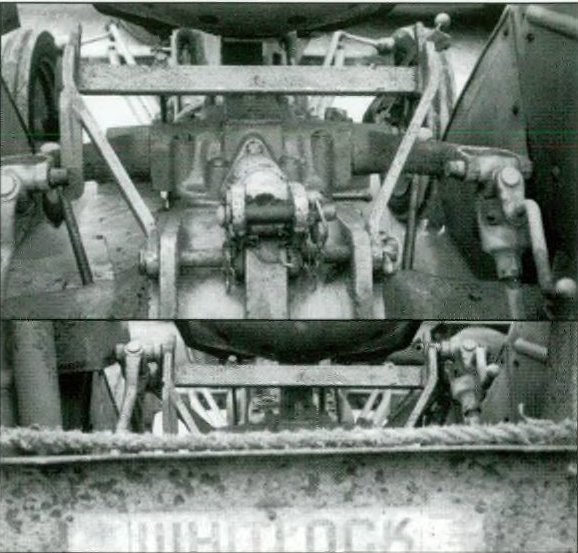
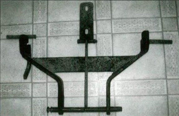
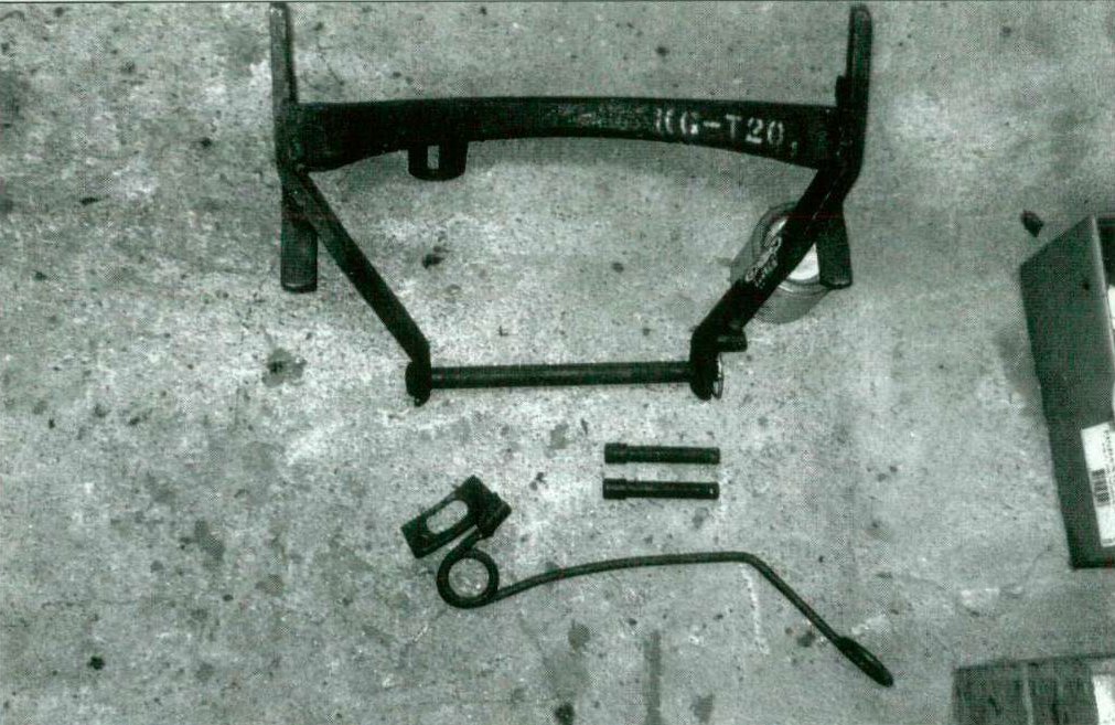 The strange implement laid out on the floor.
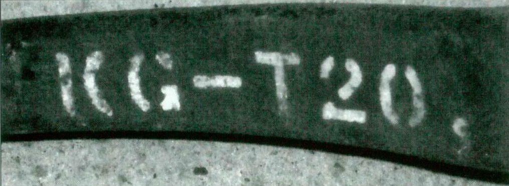 The KG-T20 wording on the side of the strange implement.