Ferguson TE20 Tractor Register database
I read Fred Turner’s article ‘The history of the Continental‘ in Journal 106 with much interest as I have two such tractors. I have also been fascinated by the fact that nobody seems to know how many were made.
We have a golden opportunity to go some way to finding out. Our membership is about 3000 so, if we who have these tractors, were to send details of their tractors to a central point in The Club, it would give us more of an idea than we have now, because quite frankly we have no idea!
So, with this in mind, and with the Chairman and Secretary’s blessing, I am volunteering to start a data base of what exists in the Club. I am proposing a data base just identifying what we have to VIN numbers only. This would NOT identify any tractor to any member. It would also try to find out how many have been converted to, say, a Perkins P3 and what condition they are in from concourse to working clothes to original unmolested condition. There would be a second data base which would be just VIN number, Member’s name and Club number.
So to kick the idea off I am asking ALL owners of TE20s to, ideally, Email to te20@fergusonclub.com their Name, Club number, TE20 VIN number and further details of condition as indicated above and anything else you wish to tell us. Of course if you have no access to a computer you can post all details to TE20 Ferguson Club, 1 The Gardens, Bury Road, Beyton, BURY ST. EDMUNDS, IP30 9AB
A report would appear each Journal as to how the project is going.
I look forward to being overwhelmed with data, please, please on this one occasion just help us help you! It will be in everyone’s interest. John Selley.
Update No.1 – February 2024, Journal No. 108
17 Respondants
21 tractors
Earliest No. 883 1947
Latest 18478 1947
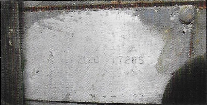
2 have no VIN plates
We even have one bought at Bangers and Cash and described as ‘presentable condition’!
John Selley.